
Cooling structure and method of magnetic suspension refrigeration compressor

A technology for refrigeration compressors and cooling structures, applied in structural connections, cooling/ventilation devices, electromechanical devices, etc., can solve problems such as motor insulation breakdown, affecting motor safety and reliability, and inability to fully characterize rotor heat dissipation conditions, so as to avoid heat dissipation The effect of harsh conditions

Pending Publication Date: 2019-08-02
TIANJIN EMAGING TECH
View PDF0 Cites 6 Cited by
  • Summary
  • Abstract
  • Description
  • Claims
  • Application Information

AI Technical Summary

Problems solved by technology

However, since the air gap temperature of the stator and rotor of the motor uses a non-contact temperature sensor, it cannot fully represent the heat dissipation conditions of the rotor, nor can it represent the actual rotor temperature.
Using this traditional temperature control method, it is not easy to determine the reference value of the motor stator and rotor air gap temperature, and it is relatively difficult to write the control program
At the same time, if the heat dissipation conditions of the motor rotor are not good, the temperature of the motor stator will be too high. Excessively high temperature of the stator winding will cause breakdown of the motor insulation, affecting the safe and reliable operation of the motor; at the same time, the temperature of the permanent magnet of the motor rotor is too high, and It will cause the rotor to demagnetize and greatly reduce the performance of the motor

Method used


Image

  • Cooling structure and method of magnetic suspension refrigeration compressor
  • Cooling structure and method of magnetic suspension refrigeration compressor
  • Cooling structure and method of magnetic suspension refrigeration compressor

Examples


Embodiment Construction

[0029] It should be noted that, in the case of no conflict, the embodiments of the present invention and the features in the embodiments can be combined with each other.

[0030] In describing the present invention, it should be understood that the terms "center", "longitudinal", "transverse", "upper", "lower", "front", "rear", "left", "right", " The orientations or positional relationships indicated by "vertical", "horizontal", "top", "bottom", "inner" and "outer" are based on the orientations or positional relationships shown in the drawings, and are only for the convenience of describing the present invention and Simplified descriptions, rather than indicating or implying that the device or element referred to must have a particular orientation, be constructed and operate in a particular orientation, and thus should not be construed as limiting the invention. In addition, the terms "first", "second", etc. are used for descriptive purposes only, and should not be interpreted...


PUM


Abstract

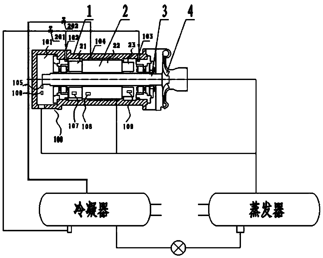
The invention provides a cooling structure and method of a magnetic suspension refrigeration compressor. The cooling structure comprises a pressure sensor Pa and temperature sensors Ta, T1, T2 and T3;a back-end sealing cavity is arranged in the back end of a motor casing, and the pressure sensor Pa and the temperature sensor Ta are arranged in the back-end sealing cavity; and the temperature sensor T1 is arranged on a stator back-end winding in the motor casing, the temperature sensor T2 is arranged on a stator core in the motor casing, and the temperature sensor T3 is arranged on a stator front-end winding in the motor casing. According to the cooling structure and method of the magnetic suspension refrigeration compressor, the internal temperature and pressure of the motor can be monitored in real time, cooling can be implemented at any time, it is ensured that a refrigerant in the motor cavity is in a saturated or slightly overheat state, and the problem that the operational reliability of the motor is influenced by that the rotor heat radiation condition is unsatisfied and the rotor temperature is too high and further a permanent magnet is demagnetized.

Description

technical field [0001] The invention belongs to the field of magnetic levitation refrigeration compressors, and in particular relates to a cooling structure and method of a magnetic levitation refrigeration compressor. Background technique [0002] Under the existing technical conditions, the cooling control method of the magnetic levitation refrigeration compressor is generally to collect the air gap temperature of the motor stator and rotor, and control the opening and closing of the motor cooling valve through a certain control logic. However, since the air gap temperature of the motor stator and rotor adopts a non-contact temperature sensor, it cannot fully represent the heat dissipation conditions of the rotor, nor can it represent the actual rotor temperature. Using this traditional temperature control method, it is not easy to determine the reference value of the motor stator and rotor air gap temperature, and it is relatively difficult to write the control program. ...

Claims


Application Information

Patent Timeline
Patent Type & Authority Applications(China)
IPC IPC(8): H02K9/19H02K11/20H02K11/25F04D29/58
CPCH02K9/19H02K11/20H02K11/25F04D29/5806F04D29/5846
Inventor 谭明忠沙宏磊俞天野潘洪涛沈虹付建伟李浩赵运磊韩景超
Owner TIANJIN EMAGING TECH
Learn More