RBCOT-BUCK circuit and method for improving transient response and high stability

A RBCOT-BUCK, high-stability technology, applied in electrical components, regulating electrical variables, output power conversion devices, etc., can solve problems such as increasing design complexity, affecting load transient response performance, etc., to eliminate mutual constraints, The effect of reducing design difficulty and improving performance

Active Publication Date: 2019-08-02
CHENGDU YICHONG WIRELESS POWER TECH CO LTD
View PDF5 Cites 7 Cited by
  • Summary
  • Abstract
  • Description
  • Claims
  • Application Information

AI Technical Summary

Problems solved by technology

However, the addition of compensation current ripple will affect the load transient response performance to a certain extent, which requires the balance between load response and loop stability to be taken into account when designing the loop, which greatly increases the design complexity. the complexity

Method used


Image

  • RBCOT-BUCK circuit and method for improving transient response and high stability
  • RBCOT-BUCK circuit and method for improving transient response and high stability
  • RBCOT-BUCK circuit and method for improving transient response and high stability

Examples


Embodiment 1

[0020] Embodiment 1: To eliminate the output feedback voltage ripple signal and reduce the impact of its delay on the system loop, it is necessary to generate a compensation ripple signal that is opposite in phase to the feedback voltage ripple and has a similar / same amplitude for superimposition, or Generate a compensation ripple with the same phase and similar amplitude as the feedback voltage ripple (the phase delay of the feedback voltage ripple signal will be completely offset when it is the same, and the phase delay of the feedback voltage ripple signal will be partially offset when it is similar) The signal is cancelled. In this embodiment, the compensating ripple signal generating unit (ripple canceling circuit) is arranged in the inner loop of RBCOT, and the output signal of the ripple canceling circuit and the output feedback voltage ripple signal of RBCOT are superimposed and connected to the inner loop of RBCOT . In this way, the entire system loop is completely c...

Embodiment 2

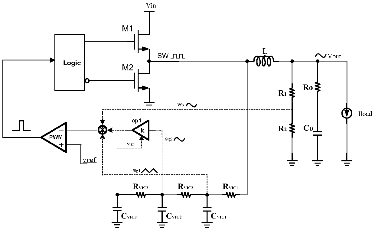
[0021] Embodiment 2: On the basis of Embodiment 1, the ripple cancellation circuit includes a first filter circuit, a second filter circuit, a third filter circuit, an internal ripple amplifier, and the RBCOT external output circuit is provided with a voltage dividing resistor circuit. After the output voltage is divided, the feedback voltage ripple signal is obtained, and the output signal of the SW end of the RBCOT internal loop passes through the first filter circuit, the second filter circuit, and the third filter circuit in sequence, and sequentially generates signal sig1, signal sig2, signal sig3, the first filter circuit is used to generate the signal sig1 as the internal feedback signal of the RBCOT system, the signal sig3 is input to the internal ripple amplifier to control the amplification factor of the internal ripple, and the feedback voltage ripple signal / signal sig2 is combined with the signal sig2 after passing through the amplifier / The feedback voltage ripple...

Embodiment 3

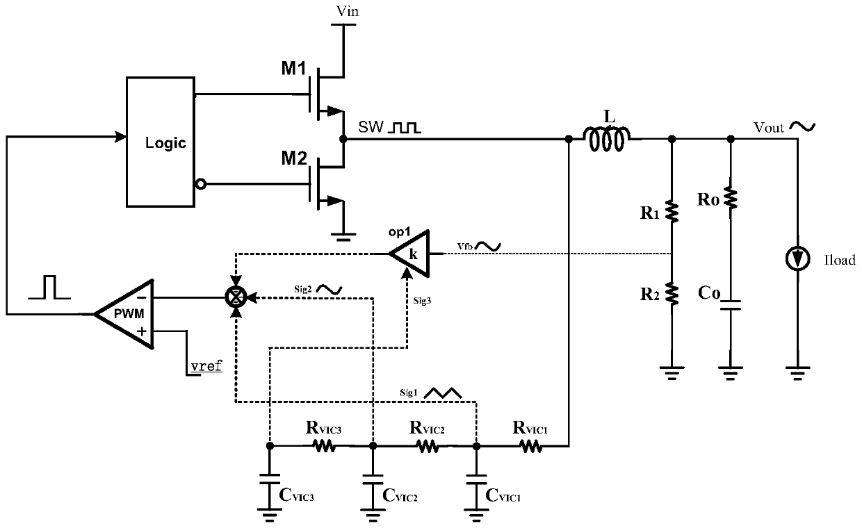
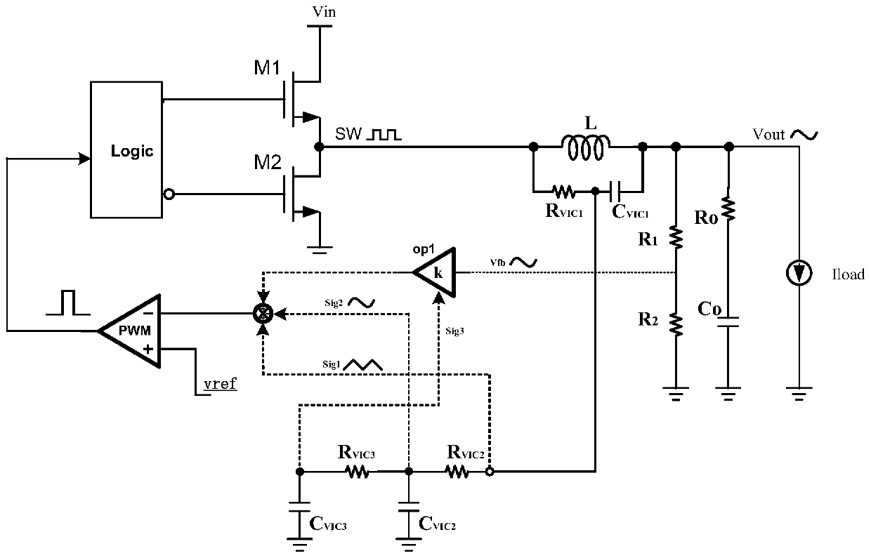
[0040] Embodiment 3: On the basis of Embodiment 1, the ripple cancellation circuit includes a first filter circuit, a second filter circuit, and a third filter circuit, and the output signal of the SW end of the RBCOT internal loop passes through the first filter circuit in sequence. circuit, a second filter circuit, and a third filter circuit, and sequentially generate signal sig1, signal sig2, and signal sig3, the first filter circuit is used to generate signal sig1, and signal sig1 subtracts signal sig3 to obtain triangular wave signal sig5 as an internal feedback signal , the signal sig2 is subtracted from the signal sig3 to obtain the sinusoidal signal sig4, and the output voltage of the external output circuit of the RBCOT is sampled as the output feedback voltage ripple signal of the RBCOT, and the output feedback voltage ripple signal of the RBCOT is subtracted from the sinusoidal signal sig4 to cancel, and after the cancellation The signal and the internal feedback sig...


PUM


Abstract

The invention relates to the technical field of power supply chips, and discloses an RBCOT-BUCK circuit for improving transient response and high stability. The RBCOT-BUCK circuit comprises an RBCOT internal loop and an RBCOT external output circuit, and further comprises a ripple cancellation circuit, wherein the ripple cancellation circuit is arranged in the RBCOT internal loop and used for generating a compensation ripple signal with the amplitude being identical or close to that of an output feedback voltage ripple signal of the RBCOT and the phase being opposite to that of the output feedback voltage ripple signal of the RBCOT, and an output signal of the ripple cancellation circuit is superimposed with the output feedback voltage ripple signal of the RBCOT and then connected to the RBCOT internal loop. According to the technical scheme of the invention, the compensation ripple signal is generated in the RBCOT internal loop, and the stability of the RBCOT loop is greatly improvedthrough cancelling the feedback voltage ripple; and meanwhile, the load transient response performance of the RBCOT structure is enhanced, and the mutual restriction between the transient response performance of the RBCOT and the stability of the loop is effectively eliminated. The load transient performance of the circuit is can be pushed to the limit, the design difficulty is greatly reduced, and the performance of the RBCOT structure is improved.

Description

technical field [0001] The invention relates to the technical field of power chips, in particular to an RBCOT-BUCK circuit and method with improved transient response and high stability. Background technique [0002] The current DC-DC power chip has higher and higher requirements on the load transient characteristics, and it is necessary to maintain the stability of the output voltage under the rapid change of the load. This makes the ripple-based constant on-time (RBCOT) control mode widely used in current buck circuit designs. [0003] The RBCOT structure controls the switch of the power tube by directly inputting the external voltage feedback signal and the internal reference voltage into the comparator for comparison. The ability to quickly change the switch duty cycle during a load step enables fast load transient response. However, due to the delay of the external voltage feedback signal, it has a great impact on the loop stability in the negative feedback system. I...

Claims


Application Information

Patent Timeline
Patent Type & Authority Applications(China)
IPC IPC(8): H02M3/158
CPCH02M3/158H02M1/0038
Inventor 贺江平金学成
Owner CHENGDU YICHONG WIRELESS POWER TECH CO LTD
Why Eureka
Try Eureka