Al technical title is built by PatSnap Al team. It summarizes the technical point description of the patent document.
A soil improvement and equipment technology, applied in the field of soil remediation, can solve the problems of inconvenience, poor soil crushing effect, inconvenient adjustment of the height of the conveyor rack and soil rack, etc., and achieve the effect of improving the crushing effect
Inactive Publication Date: 2019-08-06
田艺江
View PDF11 Cites 10 Cited by
Summary
Abstract
Description
Claims
Application Information
AI Technical Summary
This helps you quickly interpret patents by identifying the three key elements:
Problems solved by technology
Method used
Benefits of technology
Problems solved by technology
[0007] In order to solve the above-mentioned technical problems, the present invention provides a movable equipment for soil improvement to solve the problem that the existing equipment for soil improvement does not have the ability to collect the soil on the ground, and the soil on the ground has a poor crushing effect. , it is inconvenient to adjust the height of the conveying frame and the soil turning frame, it is inconvenient to adjust the injection speed, and it is not convenient to scrape and move the discharged soil.
Method used
Image
Click on the blue label to locate the original text in one second.
Reading with bidirectional positioning of images and text.
Examples
Embodiment
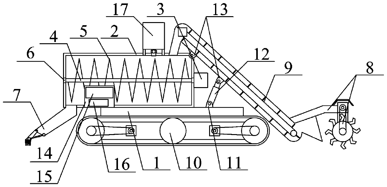
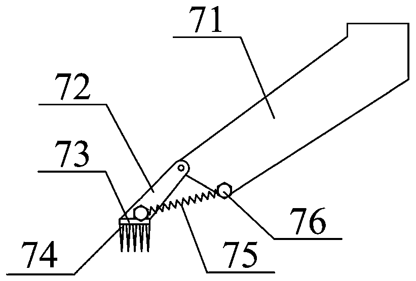
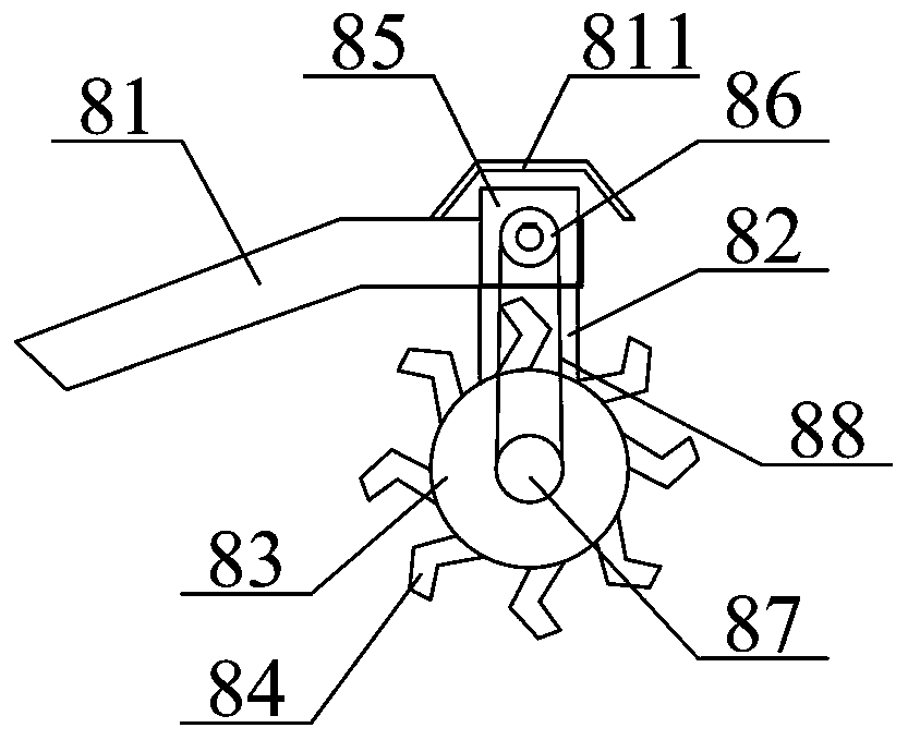
[0045] as attached figure 1 , attached image 3 And attached Figure 4 shown
[0046] The invention provides a movable equipment for soil improvement, which includes a transverse frame 1, a stirring mixing box 2, a stirring motor 3, a rotating sleeve 4, a spiral stirring blade 5, a ball bearing 6, and a discharge buffer scraper structure 7 , soil crushing frame structure 8, soil conveying frame structure 9, movable underframe structure 10, bottom shaft frame 11, telescopic cylinder 12, upper side shaft frame 13, control box 14, touch screen 15, controller 16 and feeding box structure 17 , the bolts of the mixing box 2 are installed on the upper left side of the transverse frame 1; the bolts of the stirring motor 3 are installed on the right side of the middle of the mixing box 2; the rotating sleeve 4 is inserted into the ball bearing 6 The inner ring is connected with the left output shaft of the stirring motor 3 on the right; the spiral stirring blade 5 is welded on the o...
PUM
Abstract
The invention provides movable equipment for soil improvement. The equipment comprises a transverse frame, a stirring mixing box, a stirring motor, a rotating sleeve, spiral stirring blades, a ball bearing, a discharge buffering scraper structure, a soil crushing frame structure, a soil conveying frame structure, a movable bottom frame structure, a bottom shaft frame, a retractable air cylinder, an upper side shaft frame, a control box, a touch screen, a controller and a feeding box structure, wherein the stirring mixing box is mounted on the left side of the upper portion of the transverse frame through bolts. Through arrangement of soil overturning teeth, improvement of the crushing effect on soil blocks in soil is facilitated; through arrangement of the upper side shaft frame, a material conveying frame, the stirring mixing box, the retractable air cylinder and a lower side shaft frame, convenience is provided for opening the retractable air cylinder to make the retractable air cylinder move upward to reach the height of the right side of the material conveying frame during use, and at the same time, the height of the entire soil crushing frame structure is increased so that thesituation can be avoided that the soil overturning teeth are in contact with a road surface and thus movement is affected during use of the equipment on the normal road surface.
Description
technical field [0001] The invention belongs to the technical field of soil restoration, and in particular relates to a movable device for soil improvement. Background technique [0002] Soil is the natural base for plant growth and reproduction, the basic survival material of agriculture, and the basis for human survival. With the continuous increase of my country's population and the continuous acceleration of industrialization, the accompanying pollution problems are becoming more and more serious. Among them, soil pollution is an increasingly prominent pollution problem. Nearly 1 / 5 of China's existing cultivated land is polluted to varying degrees. Polluted soil will lead to crop yield reduction, and may even cause excessive pollutants contained in agricultural products, which in turn will endanger the human body. Health, at present, soil improvement and restoration can be roughly divided into physical, chemical, biological and other methods. [0003] The Chinese patent a...
Claims
Application Information
Patent Timeline
Application Date:The date an application was filed.
Publication Date:The date a patent or application was officially published.
First Publication Date:The earliest publication date of a patent with the same application number.
Issue Date:Publication date of the patent grant document.
PCT Entry Date:The Entry date of PCT National Phase.
Estimated Expiry Date:The statutory expiry date of a patent right according to the Patent Law, and it is the longest term of protection that the patent right can achieve without the termination of the patent right due to other reasons(Term extension factor has been taken into account ).
Invalid Date:Actual expiry date is based on effective date or publication date of legal transaction data of invalid patent.