Minimally invasive ultrasonic scalpel head and minimally invasive ultrasonic bone dynamic system
A power system and ultrasonic technology, applied in the field of medical devices, can solve problems such as limited operating space and inability to remove the hole lens, and achieve the effects of good grinding or cutting, improved bone removal efficiency, and more operating space
- Summary
- Abstract
- Description
- Claims
- Application Information
AI Technical Summary
Problems solved by technology
Method used
Image

Examples
Embodiment approach 1
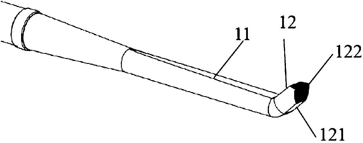
[0035] Such as figure 1 As shown, this embodiment discloses a minimally invasive ultrasonic knife head 1, which includes a knife bar 11 and a head end 12, the head end 12 is located at the front end of the knife bar 11, and the head end 12 is bent to the side at a certain angle. The bottom surface 121 of the curved portion is a square arc surface, and knurled teeth are provided on the upper and lower slopes of the transverse surface 122 of the curved portion.
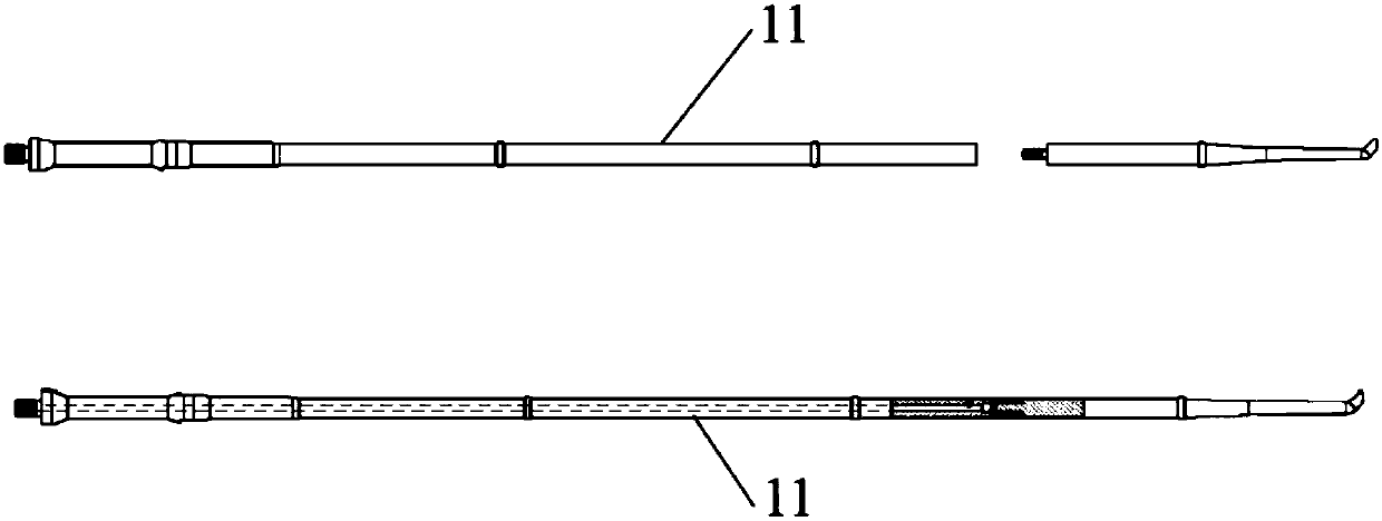
[0036] During the assembly process, since the curved head end cannot pass through the channel of the foramina, in order to enable the minimally invasive ultrasonic knife head 1 to work with the foramina, as figure 2 As shown, the knife rod 11 of the minimally invasive ultrasonic knife head is divided into two parts, that is, the front half connected to the head end 12 and the second half connected to the ultrasonic handle. These two parts are connected by threads, and the threads can tightly connect the front half and...
Embodiment approach 2
[0041] Figure 6 It is the minimally invasive ultrasonic cutter head 2 according to the second embodiment of the present invention. The cutter head 2 includes a cutter bar 21 and a head end 22. The head end 22 is located at the front end of the cutter bar 21. The head end 22 is bent to the side at a certain angle. The head end 22 is rake-shaped with helical teeth on the transverse face 222 of the curved portion.
[0042]Similar to Embodiment 1, in order to facilitate assembly, the knife bar 21 is also divided into two parts, namely the front half connected to the head end 22 and the second half connected to the handle, and the two parts are connected by threads. The cutter bar 21 can be a hollow structure, and water can be poured directly at the head end; or only a part can be a hollow structure, and water can be discharged through a side hole in the middle of the cutter bar.
[0043] The minimally invasive ultrasonic cutter head 2 can also be used in a minimally invasive ult...
Embodiment approach 3
[0045] Figure 7 It is the minimally invasive ultrasonic cutter head 3 according to the third embodiment of the present invention. The cutter head 3 includes a cutter bar 31 and a head end 32. The head end 32 is located at the front end of the cutter bar 31. The head end 32 is bent to the side at a certain angle. The head end 32 is spoon-shaped, with knurled teeth on the top surface 324 of the curved portion. Further, helical teeth can be provided on the lateral surface 322 and the side surface 323 of the curved portion.
[0046] Similar to Embodiment 1, in order to facilitate assembly, the tool bar 31 is also divided into two parts, namely the front half connected to the head end 32 and the second half connected to the handle, and the two parts are connected by threads. The cutter bar 31 can be a hollow structure, and water can be poured directly at the head end; or only a part can be a hollow structure, and water can be discharged through a side hole in the middle of the cu...
PUM
 Abstract
Description
Claims
Application Information
 - R&D
- Intellectual Property
- Life Sciences
- Materials
- Tech Scout
- Unparalleled Data Quality
- Higher Quality Content
- 60% Fewer Hallucinations
Browse by: Latest US Patents, China's latest patents, Technical Efficacy Thesaurus, Application Domain, Technology Topic, Popular Technical Reports.
© 2025 PatSnap. All rights reserved.Legal|Privacy policy|Modern Slavery Act Transparency Statement|Sitemap|About US| Contact US: help@patsnap.com