
Craniocerebral surgery post-traumatic nursing device

A nursing device and trauma technology, applied in the medical field, can solve the problems of reducing the speed of patient recovery, aggravating the patient's condition, undertaking and other problems, to achieve the effect of speeding up the speed, reducing the workload, and avoiding cross-infection

Inactive Publication Date: 2019-08-06
刘艳
View PDF0 Cites 0 Cited by
  • Summary
  • Abstract
  • Description
  • Claims
  • Application Information

AI Technical Summary

Problems solved by technology

[0002] Brain tumors refer to new organisms growing in the cranial cavity, also known as intracranial tumors and brain cancers, which can originate from the brain, meninges, nerves, blood vessels, and brain appendages, or form by metastasizing from other tissues or organs of the body into the brain , Most of them can cause headache, intracranial hypertension and focal symptoms. The treatment measures for brain tumors can be divided into surgical treatment, radiotherapy and chemical drug treatment. The treatment measures taken for different patients are different, but surgical resection of tumors It is the main treatment method. Nursing devices need to be used after craniocerebral trauma, but the existing craniocerebral post-traumatic nursing devices also have the following problems; 1. When the patient vomits after the operation, the patient's vomit cannot be To undertake, the nursing staff needs to carry out the hand-held trash can, which increases the workload of the nursing staff. 2. When the patient has a high fever after the operation, the patient cannot be cooled, which reduces the speed of the patient's recovery. 3. After the operation, the patient's head needs to be treated. It is impossible to clean and disinfect the drainage tube, which may easily cause cross-infection in patients and aggravate the patient's condition

Method used


Image

  • Craniocerebral surgery post-traumatic nursing device
  • Craniocerebral surgery post-traumatic nursing device
  • Craniocerebral surgery post-traumatic nursing device

Examples


Embodiment Construction

[0020] The following will clearly and completely describe the technical solutions in the embodiments of the present invention with reference to the accompanying drawings in the embodiments of the present invention. Obviously, the described embodiments are only some, not all, embodiments of the present invention.

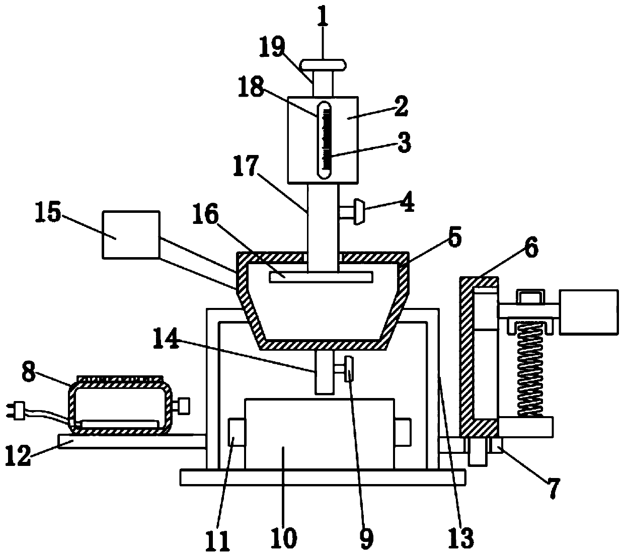
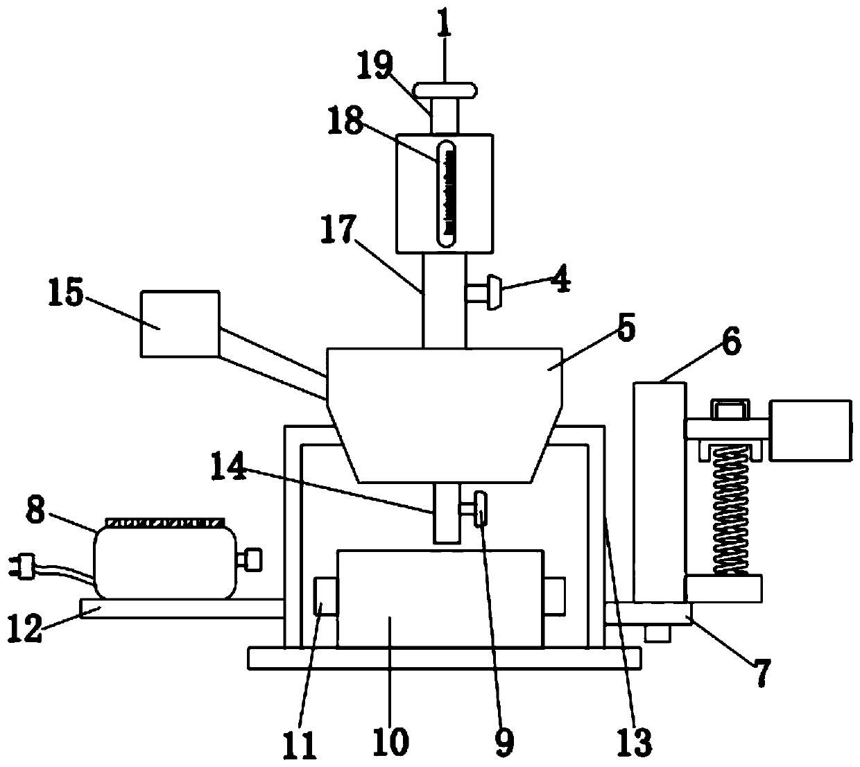
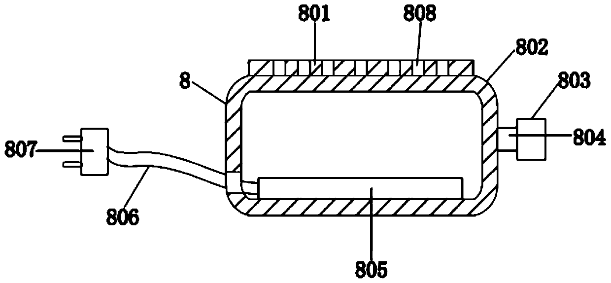
[0021] refer to Figure 1-5 , a craniocerebral surgery post-traumatic care device, comprising a receiving tube 5, the bottom of the receiving tube 5 is welded with a support seat 13 on both sides of the left and right sides, the top center of the support seat 13 is placed with a collection box 10, through The collection box 10 can collect and place the vomit, and the left and right sides of the collection box 10 are welded with handles 11, through which the discharge pipe 14 can be welded to the center of the bottom end of the receiving cylinder 5, The right side of the discharge pipe 14 is equipped with a discharge valve 9, the opening and closing of the discharge p...


PUM


Abstract

The invention discloses a craniocerebral surgery post-traumatic nursing device, which comprises a receiving cylinder, wherein support seats are welded to the left and right sides of the bottom end ofthe receiving cylinder, a collecting box is arranged at a top center position of the supporting seat, handles are welded to the left and right sides of the collecting box, a discharge pipe is welded to a center of a bottom end of the receiving cylinder, a water-collecting tank is welded to a top end of a water conduit, an inlet pipe is welded to the top end of the water-collecting tank, the top end of the inlet pipe is screwed with a cover body, the left side of the supporting seat is welded with a support plate, the top end of the support plate is placed with a cooling device, the right sideof the supporting seat is welded with a mounting plate, and a cleaning device is installed at the top of the mounting plate. The device can take the vomit of the patient, and can clean a vomit-substance, a nursing staff does not need to carry on a hand-held trash can, and the labor of the nursing staff can be saved.

Description

technical field [0001] The invention relates to the field of medical technology, in particular to a post-traumatic care device for craniocerebral surgery. Background technique [0002] Brain tumors refer to new organisms growing in the cranial cavity, also known as intracranial tumors and brain cancers, which can originate from the brain, meninges, nerves, blood vessels, and brain appendages, or form by metastasizing from other tissues or organs of the body into the brain , Most of them can cause headache, intracranial hypertension and focal symptoms. The treatment measures for brain tumors can be divided into surgical treatment, radiotherapy and chemical drug treatment. The treatment measures taken for different patients are different, but surgical resection of tumors It is the main treatment method. Nursing devices need to be used after craniocerebral trauma, but the existing craniocerebral post-traumatic nursing devices also have the following problems; 1. When the patien...

Claims


Application Information

Patent Timeline
Patent Type & Authority Applications(China)
IPC IPC(8): A61J19/00A61M25/00A61F7/10
CPCA61F7/103A61F2007/0002A61J19/00A61M25/00A61M2025/0019
Inventor 刘艳
Owner 刘艳
Learn More