A horizontal counter-wheel spinning device for forming a large thin-walled back cover structure

A horizontal, thin-walled technology used in the field of horizontal spinning devices

Active Publication Date: 2021-04-27
HARBIN INST OF TECH
View PDF10 Cites 0 Cited by
  • Summary
  • Abstract
  • Description
  • Claims
  • Application Information

AI Technical Summary

Problems solved by technology

[0003] The object of the present invention is to provide a horizontal wheel spinning device for forming a large thin-walled back cover structure, so as to solve the problems in the prior art mentioned above. The lateral movement of the guide rail is combined, and the complex spinning track is precisely formed under the combined clamping of the inner and outer wheels to the slab, thus breaking through the flexible manufacturing problem of complex and large thin-walled back cover structures

Method used


Image

  • A horizontal counter-wheel spinning device for forming a large thin-walled back cover structure
  • A horizontal counter-wheel spinning device for forming a large thin-walled back cover structure
  • A horizontal counter-wheel spinning device for forming a large thin-walled back cover structure

Examples


Embodiment Construction

[0021] The following will clearly and completely describe the technical solutions in the embodiments of the present invention with reference to the accompanying drawings in the embodiments of the present invention. Obviously, the described embodiments are only some, not all, embodiments of the present invention. Based on the embodiments of the present invention, all other embodiments obtained by persons of ordinary skill in the art without making creative efforts belong to the protection scope of the present invention.

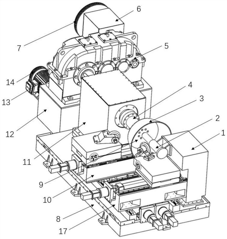
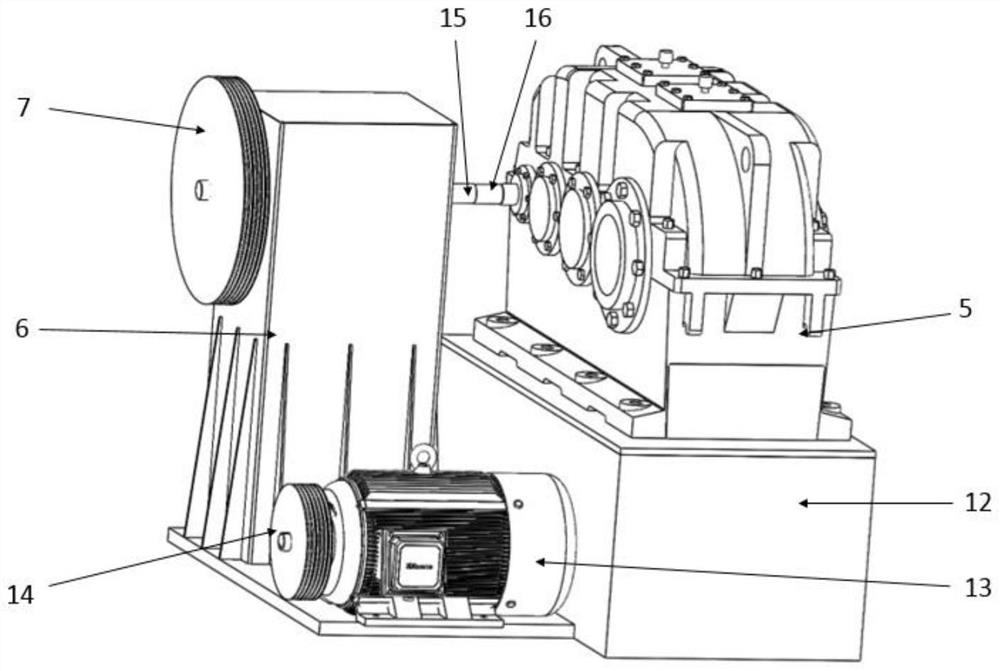
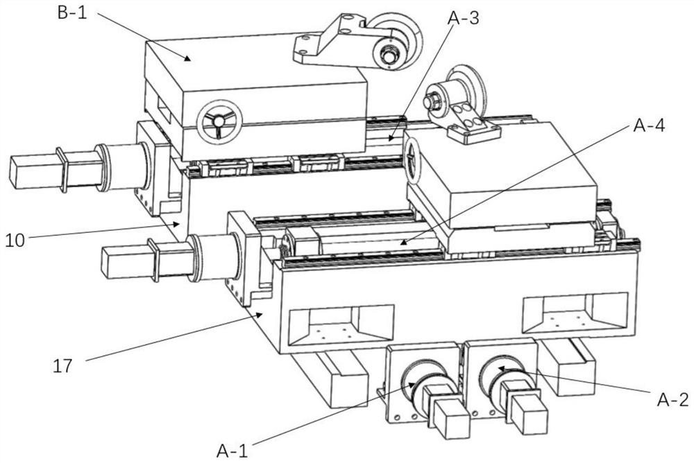
[0022] The object of the present invention is to provide a horizontal wheel spinning device for forming a large thin-walled back cover structure, so as to solve the above-mentioned problems in the prior art. The lateral movement of the guide rail is combined, and the complex spinning track is precisely formed under the combined clamping of the inner and outer wheels to the slab, thereby breaking through the flexible manufacturing problem of complex and large th...


PUM


Abstract

The invention discloses a horizontal counter-wheel spinning device for forming a large thin-walled back cover structure. In order to solve the problems of high mold cost, poor versatility and long manufacturing cycle of the existing molded spinning equipment, the internal and external spinning device of the invention The wheel mechanism is installed side by side on the base of the horizontal spinning machine, sharing two common longitudinal guide rails. The guide rails are fixed on two strip pad irons on the horizontal machine base, and a lead screw driven by a motor and a reducer is installed between the two guide rails. The motor, transmission system and reducer are installed on one side of the base of the spinning machine. The main shaft motor is connected to the input end of the reducer through the pulley, and the output end of the reducer is connected to the main shaft. The main shaft is installed on the base of the horizontal spinning machine. on the headstock. The tail top support frame is fixed on the horizontal machine base and is positioned at the side of the inner rotary wheel mechanism. The tail top base body is fixed on the side of the support frame body, and the protruding tail top apex withstands the blank fixed on the mandrel. The invention is used for spinning forming of large-scale back cover components.

Description

technical field [0001] The invention relates to the technical field of counter-wheel spinning devices, in particular to a horizontal counter-wheel spinning device for forming a large thin-walled back cover structure. Background technique [0002] The spinning forming process has unique advantages in the forming of thin-walled bottom cover structures compared with welding and deep drawing due to its advantages of simple mold, flexible process, and wide adaptability. It is currently widely used in conical covers, spherical heads, curved busbar components, etc. Manufacture of products. Most of the traditional spinning forming processes require spinning mandrels, but when the structure size of the back cover is large, the mandrelless spinning process is widely used due to its low cost and short manufacturing cycle, such as the large head parts in the petrochemical industry A large number of coreless one-step and two-step spinning methods are used. However, the traditional head...

Claims


Application Information

Patent Timeline
Patent Type & Authority Patents(China)
IPC IPC(8): B21D22/14
CPCB21D22/14
Inventor 徐文臣单德彬陈家轩陈宇矫健徐佳炜
Owner HARBIN INST OF TECH
Why Eureka
Try Eureka