Machining technology for brake drum machine

A brake drum and machining technology, which is applied in the direction of manufacturing tools, metal processing equipment, metal processing machinery parts, etc., can solve the problems of uneven force on the friction surface, increased pedal force and stroke, easy deformation, etc., to achieve improved The effects of processing yield, reducing waste loss, and stabilizing process control

Inactive Publication Date: 2019-08-06
SHENGRUI TRANSMISSION
View PDF8 Cites 2 Cited by
  • Summary
  • Abstract
  • Description
  • Claims
  • Application Information

AI Technical Summary

Problems solved by technology

[0004] The brake drum is easily deformed by heat due to structural limitations; the uneven force on the friction surface during braking also causes deformation, resulting in poor contact between the hoof and the drum, resulting in increased pedal force and stroke; the cylindricity accuracy of the working surface of the brake drum, Also cause self-locking, vibration, noise

Method used


Image

  • Machining technology for brake drum machine
  • Machining technology for brake drum machine
  • Machining technology for brake drum machine

Examples


Embodiment Construction

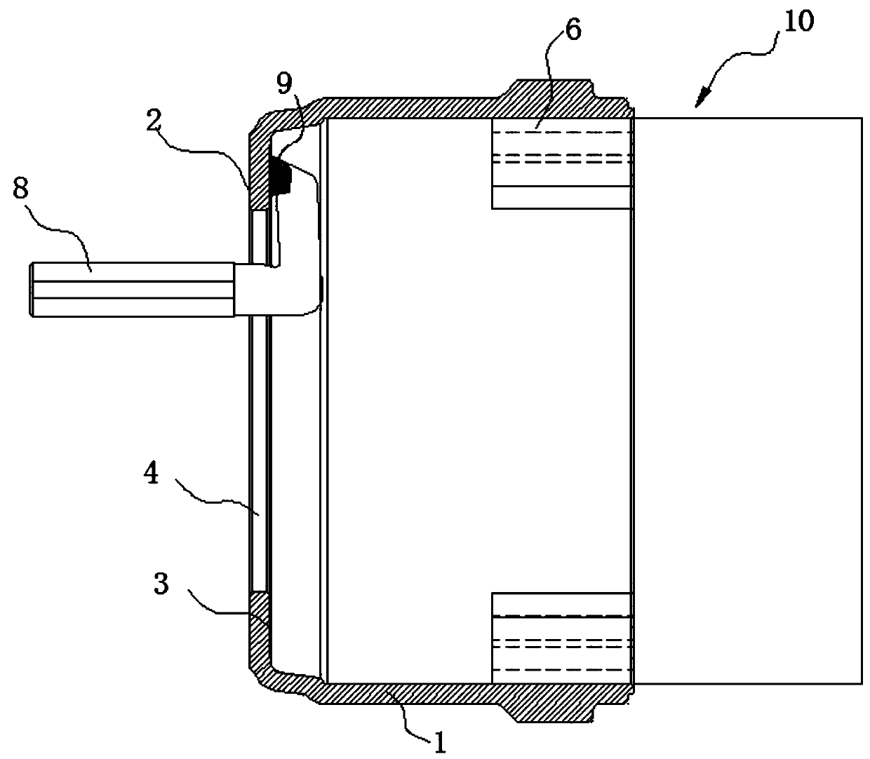
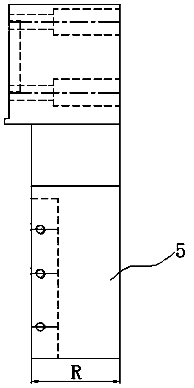
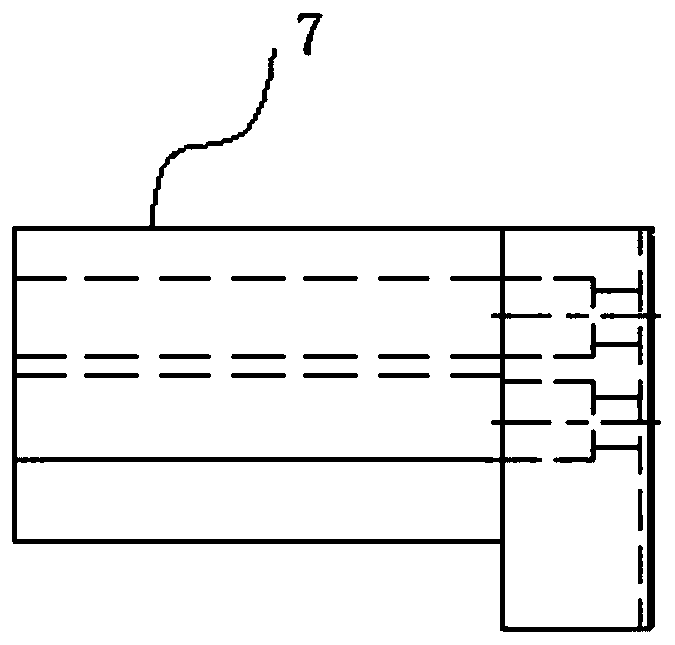
[0023] like Figure 1 to Figure 5 As shown, a brake drum machining process includes the following processing steps:

[0024] Step 1: Position and clamp the flange surface 2 and flange back surface 3 with the inner cavity of the brake drum 1 to be processed;

[0025] Step 2: Locate with the center hole 4 of the flange, press the back 3 of the flange and process the inner cavity;

[0026] Step 3: Positioning with the seam of the inner cavity, process the bolt holes on the flange surface 2.

[0027] Before proceeding to Step 1, perform the procedure of aligning the inner cavity of the brake drum. The process of aligning the inner cavity is to clamp the brake drum to be processed on the chuck of the lathe, and then slowly rotate the chuck to observe the interference between the inner cavity of the brake drum to be processed and the turning tool. If there is no interference between the drum and the turning tool, the inner cavity of the brake drum will be aligned. Due to the fun...


PUM

PropertyMeasurementUnit
diameteraaaaaaaaaa
diameteraaaaaaaaaa
Rockwell hardnessaaaaaaaaaa

Abstract

The invention discloses a machining technology for a brake drum machine. The machining technology includes the following machining steps that firstly, an inner cavity of a to-be-machined brake drum isused for machining a flange face and a flange back face in a positioning clamping manner; secondly, a flange center hole is used for positioning, the flange back face is pressed, and the inner cavityis machined; and thirdly, an inner cavity seam allowance is used for positioning, and all bolt holes of the flange face are machined. The roughness of the machined faces is effectively ensured, the brake drum machining yield and quality stability are effectively ensured, the machining yield is effectively increased, defective product losses are effectively reduced, and process control is more stable.

Description

technical field [0001] The invention relates to a brake drum machining process. Background technique [0002] The brake drum is a key part of the brake of the axle assembly of various road transport vehicles. The brake drum is a vulnerable part in the drum brake, and it is also one of the key parts that affect the safe braking of the vehicle. Its wear resistance, rigidity to withstand instantaneous braking, and uniformity of wall thickness are the performance indicators of the brake drum. The processing roughness of the braking surface of the brake drum has a great influence on the braking safety distance, noise and vibration. [0003] The optimal structure of the brake drum should be light in weight, good in rigidity, easy to process and assemble. Common brake drum structure designs include integral casting, steel plate and cast iron combination, light alloy and cast iron combination and other structures. Brake drums of various structures, especially brake drums formed b...

Claims


Application Information

Patent Timeline
Patent Type & Authority Applications(China)
IPC IPC(8): B23B5/00B23B31/10B23Q3/12
CPCB23B5/00B23B31/10B23Q3/12
Inventor 李金年赵连凯朱志鹏梁超
Owner SHENGRUI TRANSMISSION
Why Eureka
Try Eureka