Copper part thin-wall fine punching equipment

A fine blanking and thin-walled technology, applied in the field of thin-walled fine punching equipment for copper parts, can solve the problems of machine occupation, insufficient market competitiveness, and unstable process, so as to improve production efficiency, ensure process yield, and save The effect of equipment investment

Pending Publication Date: 2021-02-02
DONGGUAN LINGJIE PRECISION MACHINING TECH CO LTD
View PDF0 Cites 0 Cited by
  • Summary
  • Abstract
  • Description
  • Claims
  • Application Information

AI Technical Summary

Problems solved by technology

[0005] (1) Unstable manufacturing process: CNC process, fixing the product through jigs, processing hole positions through programs and tools, the contour and position of copper parts are unstable, and the yield rate is low; the price of copper materials is high, which seriously wastes materials and manpower Cost & equipment cost remains high, and the market competitiveness is insufficient;
[0006] (2) Manual clamping & unloading & arranging takes a long time: each fixture can

Method used


Image

  • Copper part thin-wall fine punching equipment
  • Copper part thin-wall fine punching equipment
  • Copper part thin-wall fine punching equipment

Examples


Embodiment Construction

[0033] The present invention will be described in further detail below in conjunction with the accompanying drawings.

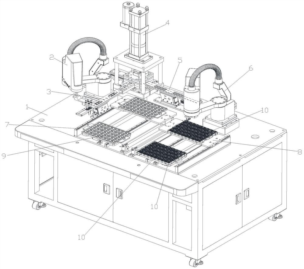
[0034] Figure 1~4 A thin-wall fine punching equipment for copper parts according to an embodiment of the present invention is schematically shown.

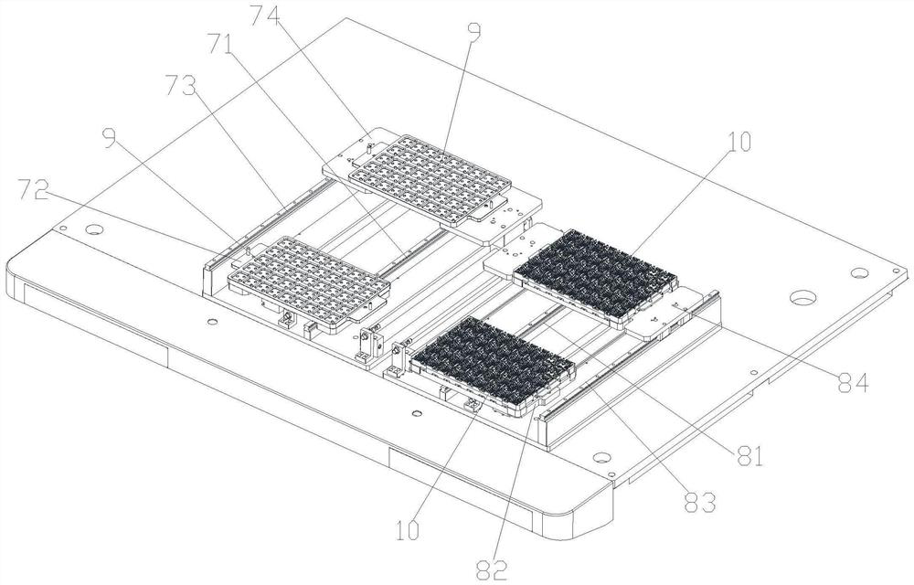
[0035] Such as Figure 1~4 As shown, the thin-wall fine punching equipment for copper parts includes a machine platform 1 and a feeding device 2 arranged on the machine platform 1, a feeding conveying channel 3, a punching device 4, a discharging conveying channel 5, a feeding device 6, The first tray device 7, the second tray device 8.

[0036] The first tray device 7 is used to place the first tray 9, and the first tray 9 is used to carry the workpiece to be punched; the second tray device 8 is used to place the second tray 10, and the second tray 10 is used for Carrying the workpiece after punching;

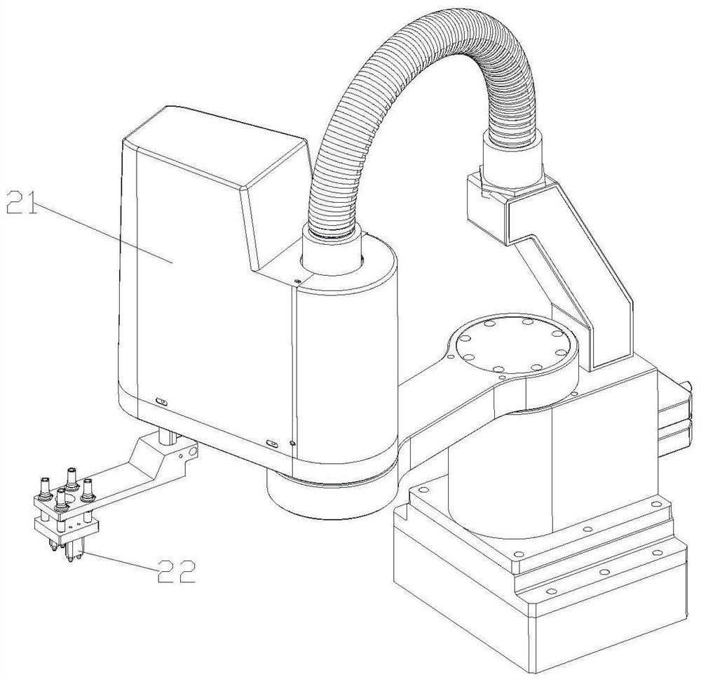
[0037] The feeding device 2 is arranged on one side of the feeding conveying channel 3, and is configured...


PUM


Abstract

The invention discloses copper part thin-wall fine punching equipment. The copper part thin-wall fine punching equipment comprises a machine table, a feeding device, a feeding conveying channel, a punching device, a discharging conveying channel, a discharging device, a first material tray device and a second material tray device. The feeding device, the feeding conveying channel, the punching device, the discharging conveying channel, the discharging device, the first material tray device and the second material tray device are arranged on the machine table; the first material tray device isused for placing a first material tray, and the first material tray is used for bearing a to-be-punched workpiece; the second material tray device is used for placing a second material tray, and the second material tray is used for bearing the punched workpiece; the feeding device is arranged on one side of the feeding conveying channel and is configured to convey the to-be-punched workpiece on the first material tray to the feeding conveying channel; the feeding conveying channel is configured to convey the to-be-punched workpiece to the punching device; the punching device is configured to punch the to-be-punched workpiece; the discharging conveying channel is configured to output the punched workpiece; and the discharging device is arranged on one side of the discharging conveying channel and used for conveying the punched workpiece to the second material tray. The equipment can realize fine punching, and is high in production efficiency and high in automation degree.

Description

technical field [0001] The invention relates to the field of punching equipment, in particular to thin-wall fine punching equipment for copper parts. Background technique [0002] 3C products have emerged along with the development of the electronics industry in recent years, mainly referring to computer, communication, and consumer electronics products. In this industry, the development of technology is changing with each passing day. , upgrades are frequent, and a large number of new products are launched almost every month, which has become a hot area of ​​product design. [0003] At present, there is a special 3C industry for 3C products. 3C products are generally formed by assembling a large number of parts. Therefore, punching is one of the indispensable processes for manufacturing these 3C products. [0004] At present, for some metals, especially copper workpieces, CNC lathes are generally used for fine punching. However, in the actual production process, there are...

Claims


Application Information

Patent Timeline
IPC IPC(8): B21D28/24B21D43/18B21D45/06
CPCB21D28/24B21D43/18B21D45/06
Inventor 袁文欢余雷廖梦雄
Owner DONGGUAN LINGJIE PRECISION MACHINING TECH CO LTD
Why Eureka
Try Eureka