
Automatic coupler welding device

An automatic welding and coupler technology, applied in welding positions, auxiliary devices, welding equipment, etc., can solve problems such as non-compliance, low efficiency, unfavorable mass production, etc., to prevent overheating and melting, improve safety and service life, and improve The effect of production efficiency

Pending Publication Date: 2019-08-06
ZHEJIANG DAWEI ELECTRONICS +1
View PDF1 Cites 0 Cited by
  • Summary
  • Abstract
  • Description
  • Claims
  • Application Information

AI Technical Summary

Problems solved by technology

However, at present, manual riveting and welding are mainly used, which has low efficiency, is not conducive to mass production, and does not meet the needs of modern automated production.

Method used


Image

  • Automatic coupler welding device
  • Automatic coupler welding device
  • Automatic coupler welding device

Examples


Embodiment Construction

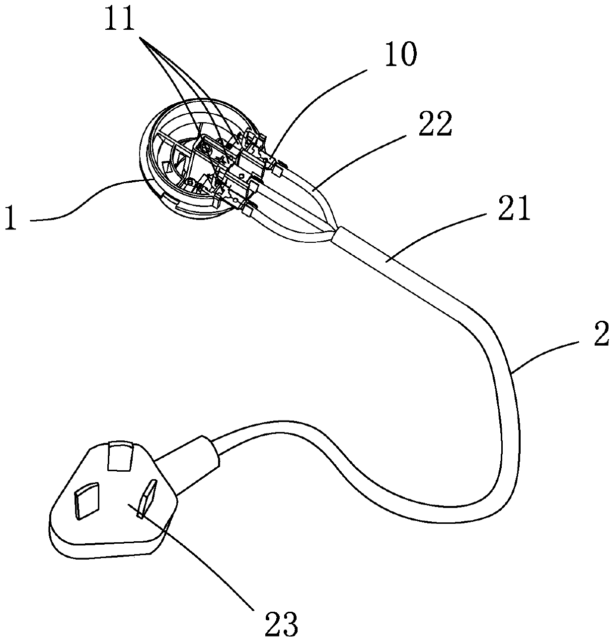
[0029] A new type of coupler developed by the applicant, such as figure 1 As shown: it includes a base 1 made of plastic and a power cord 2 connected to the base 1. The base 1 is provided with three conductive sheets 11, and the three conductive sheets 11 are respectively arranged corresponding to the ground wire, live wire and neutral wire. The power line 2 then includes a bus 21 and three branch lines 22. The three branch lines 22 are separated from one end of the bus 21 and connected to the terminals of the three conductive sheets 11 correspondingly. The exposed part of the copper wire is connected with riveting. There is a riveting place 10 between the conductive sheet 11 and the branch line 22. The other end of the bus 21 is connected to a plug 23. The exposed part of the copper wire at the end of the branch line 22 is riveted with the terminal of the conductive sheet 11. , Welding, the joints of the branch lines corresponding to the live line and the neutral line respect...


PUM


Abstract

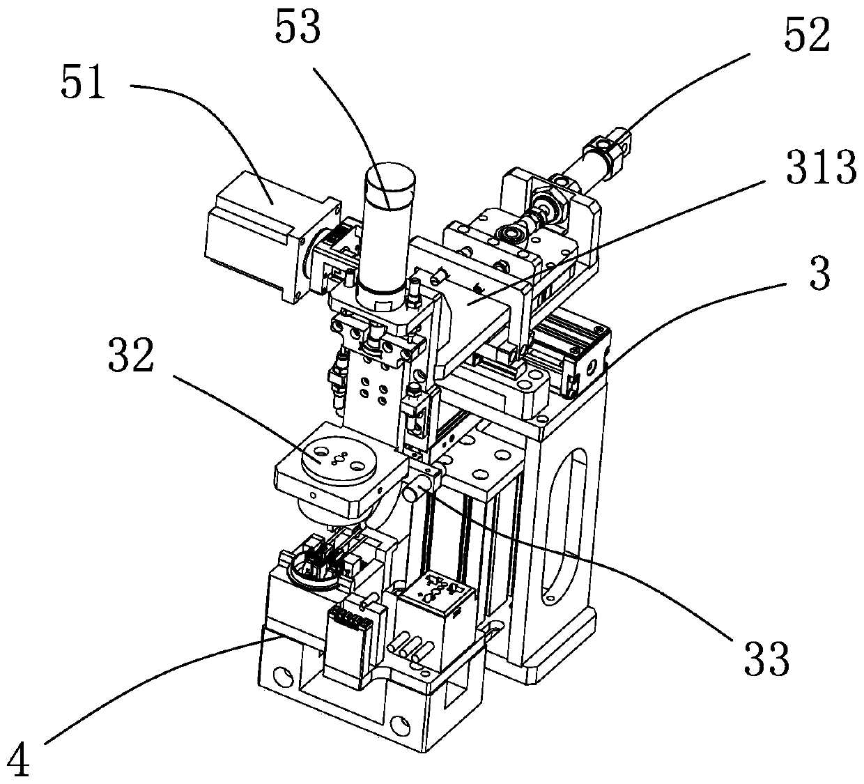
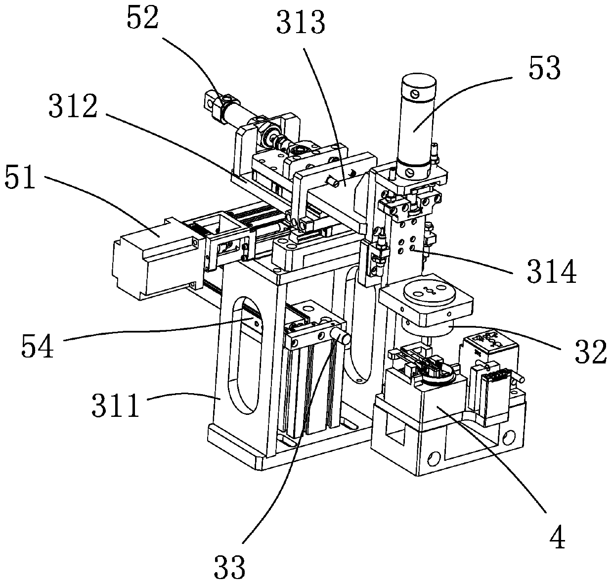
The invention discloses an automatic coupler welding device which comprises a welding mechanism and a carrier. The carrier comprises a welding groove for supporting and positioning a riveting positionbetween a conductive sheet and one end of a power line, and a conductive block in matched contact with the conductive sheet. The welding mechanism comprises a machine frame, a welding head, a conductive contact and a driving assembly, wherein the welding head, the conductive contact and the driving assembly are arranged on the support. The welding head and the conductive contact are electricallyconnected with the positive pole and the negative pole of a welding circuit correspondingly, the welding head can be driven by the driving assembly to press the riveting position between the conductive sheet and one end of the power line in the welding groove, and the conductive contact can be driven by the driving assembly to press the conductive block. The automatic coupler welding device is simple in structure, can automatically weld the riveting position of a connecting terminal of the conductive sheet and the copper wire part of a branch line, and improves the production efficiency.

Description

technical field [0001] The invention relates to an automatic welding device for a coupler. Background technique [0002] A coupler is an electrical connection unit commonly used on the base of household appliances such as an electric kettle or a wall breaker. As disclosed in CN204067589U, the coupler generally includes a base made of plastic and a power cord connected to the base. There are three conductive sheets on the seat, and the three conductive sheets correspond to the ground wire, live wire and neutral wire respectively. The power line includes a bus and three branch lines. The three branch lines are separated from one end of the bus and connected to the three conductive sheets. The other end is connected to a plug. [0003] At present, in the coupler in the prior art, the conductive sheet and one end of the power line are generally electrically connected through terminal plugging. Before the connection, the end of the branch line needs to be stripped and the copper...

Claims


Application Information

Patent Timeline
Patent Type & Authority Applications(China)
IPC IPC(8): B23K3/02B23K3/08B23K101/36
CPCB23K3/026B23K3/085B23K2101/36
Inventor 赵海杰李俊赵彬宇
Owner ZHEJIANG DAWEI ELECTRONICS
Learn More