Engine cooling system and method

A technology for engine cooling and engine temperature, applied in engine cooling, engine components, engine control, etc.

Pending Publication Date: 2019-08-06
FORD GLOBAL TECH LLC
View PDF1 Cites 5 Cited by
  • Summary
  • Abstract
  • Description
  • Claims
  • Application Information

AI Technical Summary

Problems solved by technology

Zero coolant flow with fans running results in no cooling

Method used


Image

  • Engine cooling system and method
  • Engine cooling system and method
  • Engine cooling system and method

Examples


Embodiment Construction

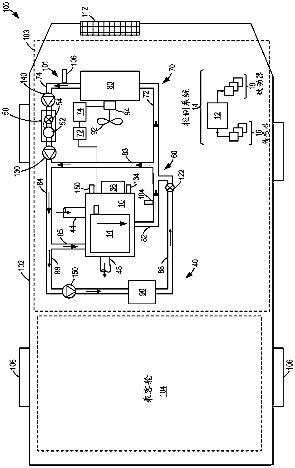
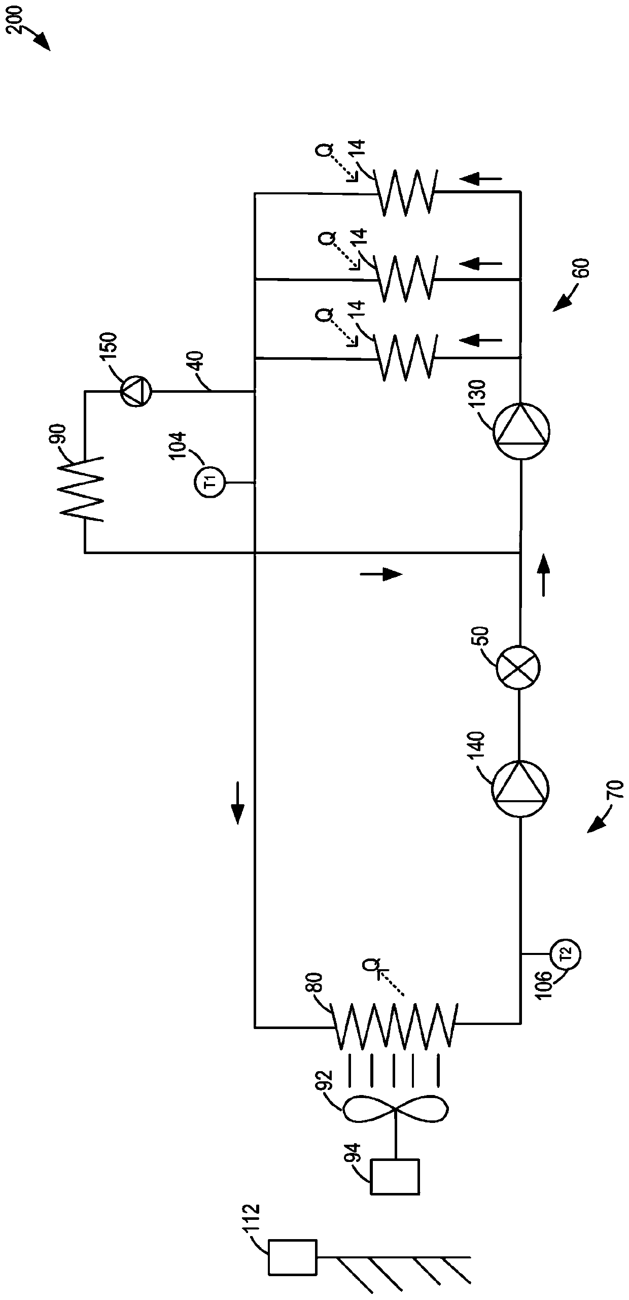
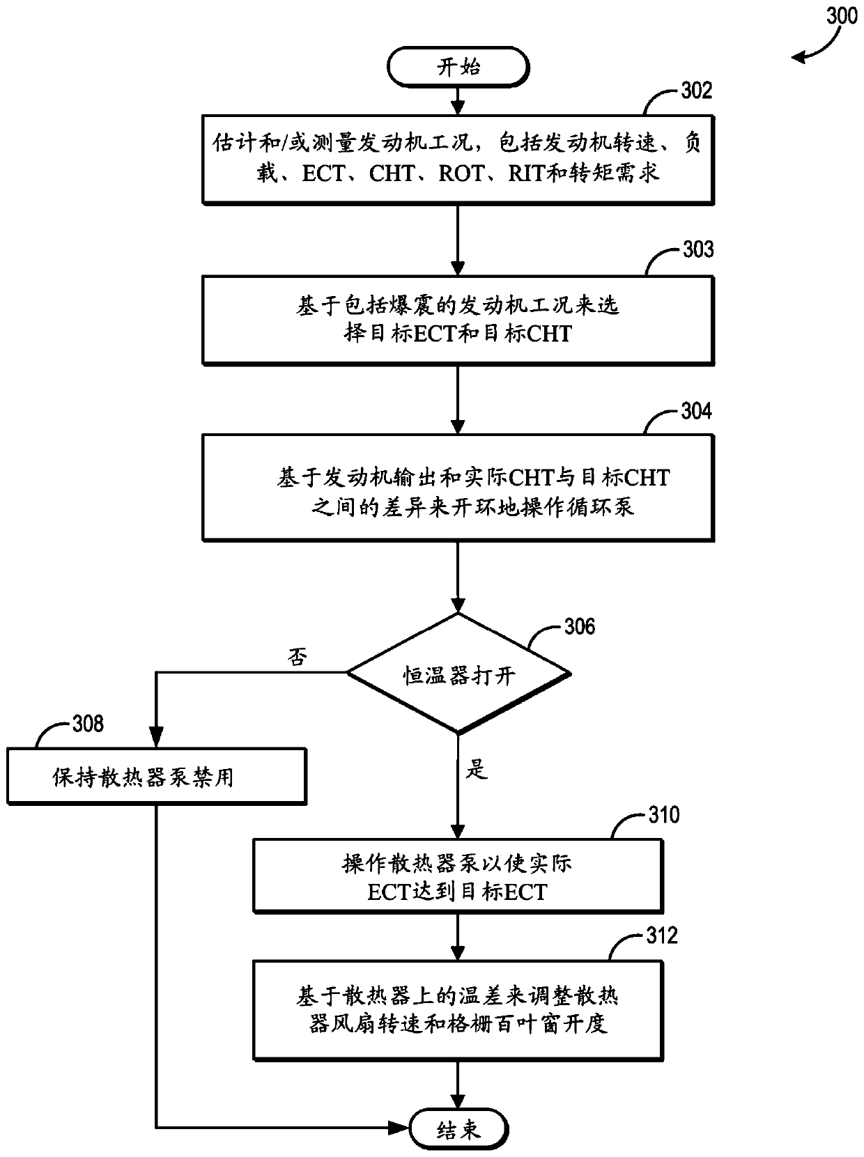
[0015] A cooling system for an engine operatively coupled to a vehicle system is provided, such as Figure 1-2 cooling system) for the method and system of engine temperature control. The engine controller can be configured to execute control routines such as image 3 An exemplary routine for facilitating engine temperature control by coordinating operation of the circulation pump and radiator pump with operation of the radiator fan and grille shutters. refer to Figure 4 Exemplary operations are shown.

[0016] figure 1 An exemplary embodiment of a vehicle system 100 is shown that includes a vehicle cooling system 101 in a motor vehicle 102 . Vehicle 102 has drive wheels 106 , a passenger compartment 104 (also referred to herein as a passenger compartment) and an under-hood compartment 103 . The under-hood compartment 103 may house various under-hood components under the hood (not shown) of the motor vehicle 102 . For example, the under-hood compartment 103 may house th...


PUM


Abstract

Methods and systems are provided for expediting engine cooling while reducing the overall energy consumption of the engine cooling system's components. A first circulation pump is used to pump coolantthrough an engine block as a function of engine output while a second radiator pump is selectively operated when a thermostat valve is open to pump coolant through a radiator and the engine block toeffect the engine coolant temperature. Operation of the second pump is coordinated with the operation of a radiator cooling fan and grille shutters to improve radiator performance.

Description

technical field [0001] The present description generally relates to methods and systems for controlling engine temperature via coordinated operation of multiple coolant pumps, radiator fans, and grille shutters. Background technique [0002] Vehicles may include a cooling system configured to reduce engine overheating by transferring heat to ambient air. In it, coolant is circulated through the engine block to remove heat from the hot engine, and the heated coolant is then circulated through the radiator near the front of the vehicle. Heated coolant may also be circulated through the heat exchanger to heat the passenger compartment. A cooling system may include various components, such as various valves and one or more thermostats. [0003] One example of an engine coolant system is shown in US 4,325,219 by Stang et al. Wherein the coolant system comprises an engine circuit and an aftercooler circuit, coolant is circulated through both circuits via a single engine driven ...

Claims


Application Information

Patent Timeline
Patent Type & Authority Applications(China)
IPC IPC(8): F01P7/16F01P5/10F01P7/02F01P7/04
CPCF01P7/165F01P5/10F01P7/04F01P7/026F01P7/164F01P7/16F01P2005/105F02D35/027F02D2200/021F02D41/062F01P3/02F01P7/10F01P7/167F01P7/048F01P2025/33F01P2025/32F01P2025/34F01P2025/36F01P2025/12F01P1/06F01P5/04F01P5/12F01P7/12F01P2003/024F01P2023/08F01P2037/00
Inventor 拉尔夫·坎宁安约瑟夫·乌雷罗斯·普西福尔
Owner FORD GLOBAL TECH LLC
Why Eureka
Try Eureka