
Engineering machinery differential lock differential mechanism

A technology for construction machinery and differentials, applied in mechanical equipment, differential transmissions, belts/chains/gears, etc., can solve problems such as the loss of differentials, and achieve the effect of avoiding rigid impact and compact structure

Pending Publication Date: 2019-08-06
XUZHOU XCMG DRIVELINE TECH CO LTD
View PDF0 Cites 1 Cited by
  • Summary
  • Abstract
  • Description
  • Claims
  • Application Information

AI Technical Summary

Problems solved by technology

In this case the differential is ineffective

Method used


Image

  • Engineering machinery differential lock differential mechanism
  • Engineering machinery differential lock differential mechanism
  • Engineering machinery differential lock differential mechanism

Examples


Embodiment Construction

[0033] The present invention will be further described below in conjunction with the accompanying drawings. The following examples are only used to illustrate the technical solution of the present invention more clearly, but not to limit the protection scope of the present invention.

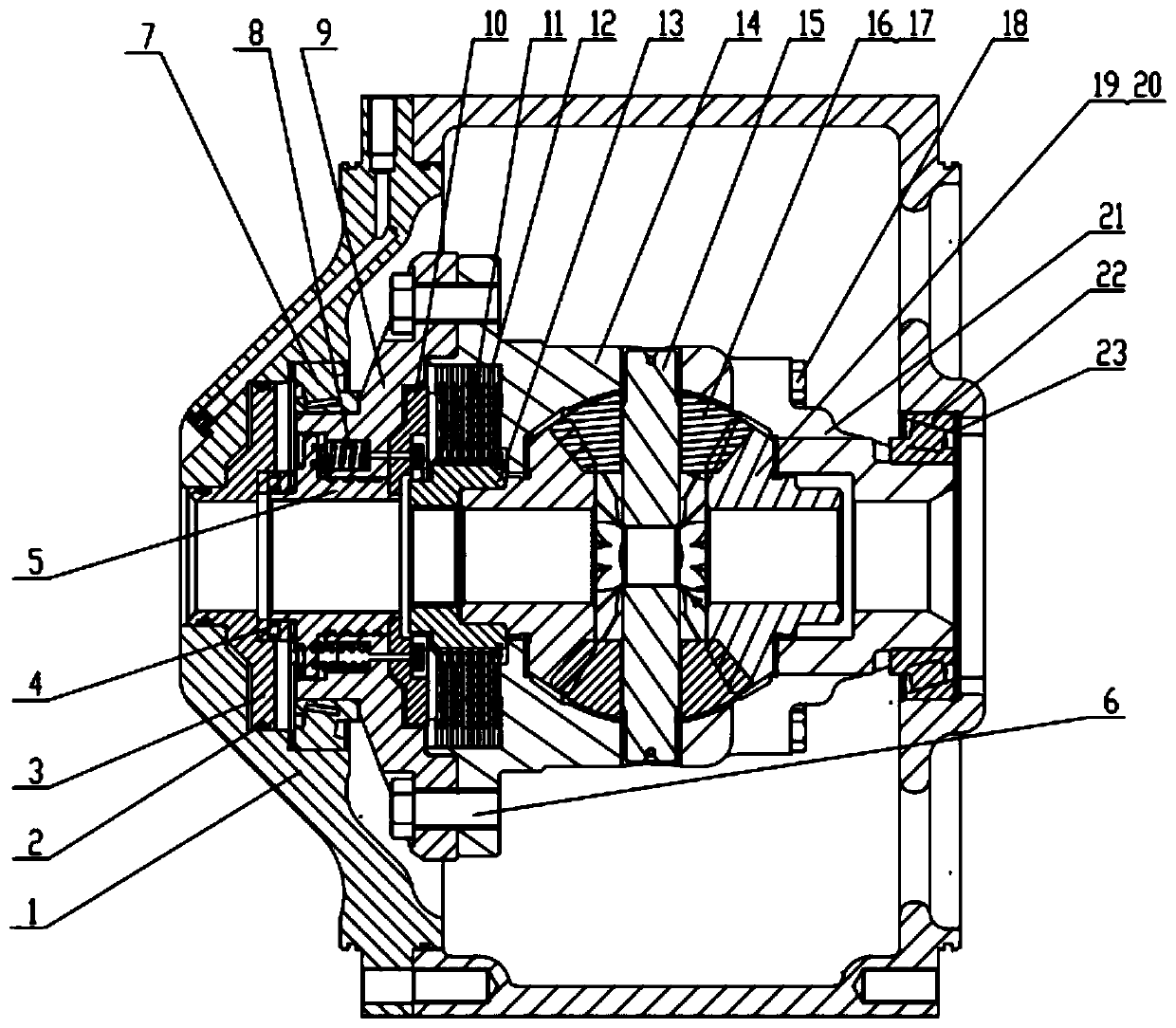
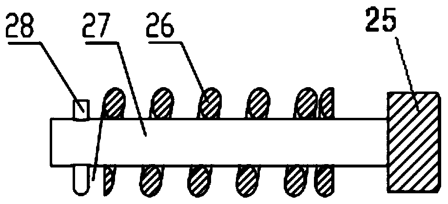
[0034] Depend on Figure 1 to Figure 4 As shown, a construction machinery differential lock differential of the present invention includes a spline sleeve 13, a pressure plate 10, a friction plate 11, a driven plate 12, and a transition sleeve 5 arranged on one half shaft of the differential. , Return spring assembly 8 and end cap 9.

[0035] Differential gear left housing 14 and differential gear right housing 21 are fixed as a whole by bolt I 18 after coupling, and cross shaft 15, planetary gear 16, planetary gear spacer 17, half shaft gear 19, half shaft are housed in its inner space. Gear spacer 20. A spline sleeve 13 which can be engaged with an external spline on the half shaft is sleev...


PUM


Abstract

The invention discloses an engineering machinery differential lock differential mechanism. The engineering machinery differential lock differential mechanism comprises a spline sleeve arranged on oneof axle shafts of the differential mechanism, a pressing disc, a friction plate group, a transition sleeve, a reset spring assembly, an end cover and a piston capable of axially moving; the inner surface of the spline sleeve can mesh with the corresponding axle shaft, and the outer surface of the spline sleeve can mesh with the friction plate group; the end cover is arranged on the outer side of the pressing disc and fixedly connected with a differential mechanism shell; the center of the end cover is provided with an inner hole used for containing the axle shaft and the transition sleeve; oneend face of the transition sleeve is adjacent to the pressing disc, and the other end face of the transition sleeve can be pushed by the piston to axially move along the axle shaft; and the end coveris provided with multiple stepped holes used for installing the reset spring assembly, and the portions, in the axial direction of the stepped holes, of the pressing disc and the transition sleeve are provided with through holes. According to the scheme, the inner cavity space of the shell is skillfully utilized for part layout, and the structure is compact; and the friction plate group meshes with the spline sleeve, and then rigid impact generated in the locking process is avoided; and the pressing disc and the friction plates are driven by the transition sleeve and a rod by means of the reset springs to be quickly separated, and therefore quick unlocking is achieved.

Description

technical field [0001] The invention relates to a construction machinery differential lock differential, which belongs to the technical field of loaders. Background technique [0002] There is a differential in the drive axle of the loader, which allows the left and right wheels to rotate at different speeds, but when one of the wheels is idling, the other wheel on a good road will not get torque. The machine loses power to drive. In this case the differential is useless. In order to improve the passing capacity of the loader on slippery roads, it is necessary to lock the differential, which can make the wheels on both sides of the drive axle rigidly connected, and can transmit most of the torque or even all the torque to the wheels that do not slip, thereby Allow the machine to generate sufficient traction to continue driving. Contents of the invention [0003] In view of the above-mentioned problems, the present invention provides a construction machinery differential...

Claims


Application Information

Patent Timeline
IPC IPC(8): F16H48/22F16H48/38
CPCF16H48/22F16H48/38
Inventor 雷雄波衡芳芳吕培新龚滏生殷浩东曹庆环曾庆星
Owner XUZHOU XCMG DRIVELINE TECH CO LTD
Learn More