Tamper body structure of vibro-rammer

A technology of vibrating rammer and driving mechanism, which is applied in infrastructure engineering, rotary piston type/oscillating piston type pump components, soil protection, etc., and can solve problems such as increased construction cost and maintenance cost, construction delay, hydraulic oil leakage, etc. , to achieve the effect of reducing the cost of tamping and maintenance, prolonging the service life and improving the efficiency of vibration

Inactive Publication Date: 2021-12-28
山东北国宏峰机电科技有限公司
View PDF0 Cites 0 Cited by
  • Summary
  • Abstract
  • Description
  • Claims
  • Application Information

AI Technical Summary

Problems solved by technology

[0004] The use of an external power hydraulic motor not only has a large volume of the tamp body, but also the hydraulic motor is easily touched and prone to failure when it is in a vibrating state, especially in a harsh working environment. In addition, the drive shaft of the hydraulic motor and the tamp body need to be S

Method used


Image

  • Tamper body structure of vibro-rammer
  • Tamper body structure of vibro-rammer
  • Tamper body structure of vibro-rammer

Examples


Embodiment 1

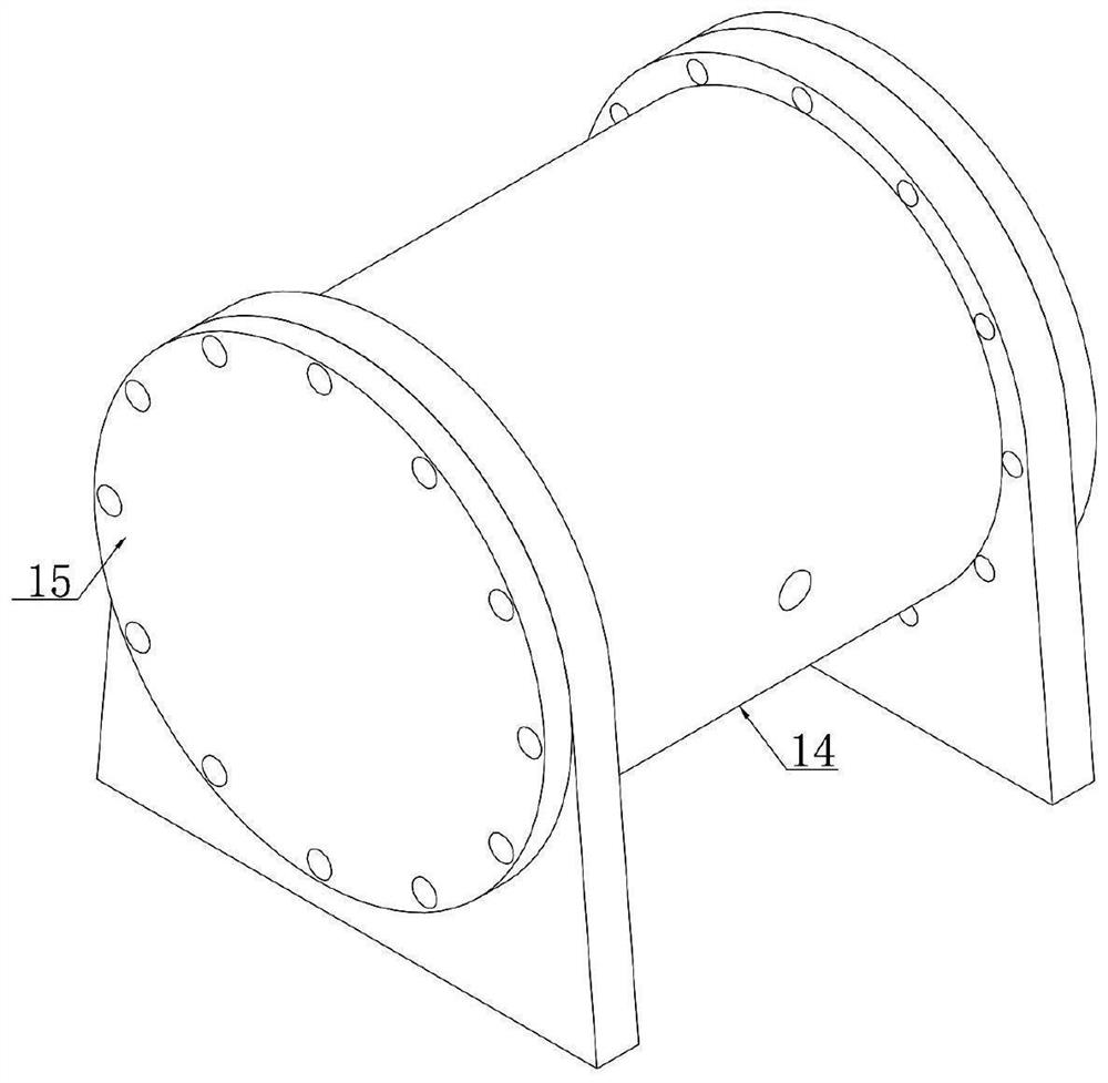
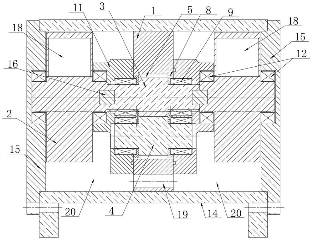
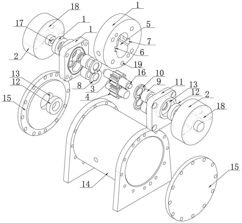
[0043] Example 1, such as Figure 1-Figure 9 As shown, a ram body structure of a vibrating rammer includes a box body, an eccentric mechanism and a driving mechanism for driving the eccentric mechanism to rotate, the driving mechanism is arranged between the eccentric mechanisms, and the eccentric mechanism includes an eccentric wheel 2 ;

[0044] The drive mechanism includes a pump body 1 located in the casing, a pump cover 11 located on both sides of the pump body 1, a driving gear 3 and a driven gear 4 meshed with the driving gear 3, and the pump body 1 is welded to the In the box, the pump cover 11 is installed on the pump body 1 through bolts, and there is a sealing ring between the two. The pump body 1 and the pump cover 11 form a pump chamber 5, and the driving gear 3 and the driven gear 4 are arranged on the pump body. In the pump cavity 5, an inlet and an outlet are correspondingly provided on the casing and the pump body 1 on both sides of the driving gear 3 and the...

Embodiment 2

[0054] Example 2, such as Figure 10 and Figure 11 As shown, the pump body is provided with at least one oil return hole 21, the oil return hole communicates with the inlet, outlet and / or pump cavity on the pump body, and a check valve is arranged in the oil return hole (not shown in the figure). The cooperation of the one-way valve and the oil return hole allows the hydraulic oil in the eccentric chamber to enter the pump body to drive the gear to rotate, not only can discharge the hydraulic oil in the eccentric chamber to act on the gear to provide power, but also does not need to add additional The hydraulic oil discharge port increases the points that are easy to be damaged, which is more conducive to the maintenance of the tamping body and reduces maintenance costs.

[0055] The drive of the eccentric mechanism is set inside the box body, and the hydraulic oil enters the pump cavity from the inlet on one side of the box body and the pump body, and is discharged through...


PUM


Abstract

The invention discloses a rammer body structure of a vibro-rammer. The rammer body structure comprises a box body, an eccentric mechanism and a driving mechanism, and the eccentric mechanism comprises an eccentric wheel; and the driving mechanism comprises a pump body, a pump cover, a driving gear and a driven gear, the driving gear and the driven gear are arranged in a pump cavity formed by the pump body and the pump cover, an inlet and an outlet are correspondingly formed in the box body and the pump body, the two ends of a wheel shaft of the driving gear are rotationally connected with the pump cover correspondingly, the shaft end of the driven gear extends out of the pump cover and is connected with one end of a wheel shaft of the eccentric wheel, the other end of the wheel shaft of the eccentric wheel is rotatably connected with the box body, and the two ends of a wheel shaft of the driven gear are rotatably connected with the pump cover correspondingly. A hydraulic motor is not needed on the outer side of the box body, the structure is simple, driving is convenient, the rammer body cost and the maintenance cost are reduced while the rammer body vibration requirement is met, driving is not prone to failing, hydraulic oil leakage is prevented, and the service life of the vibro-rammer is prolonged.

Description

technical field [0001] The invention relates to a vibratory rammer body structure, which belongs to the technical field of construction engineering. Background technique [0002] At present, in large-scale construction projects such as highways, railways, and hydropower, large-scale road rollers are often used for large-scale compaction operations, while small-scale vibratory compaction machines or vibratory plate compactors are used for narrow-area and small-scale earthwork compaction operations. [0003] The existing vibratory plate compactor has its own power system, which is mostly driven by an external hydraulic motor. The hydraulic motor is installed outside the tamp body, and its driving end extends into the tamp body to provide power for the rotation of the eccentric mechanism. The eccentric mechanism realizes the amplitude of the centrifugal force. The movement generates vibrations to achieve the effect of loosening and compacting the ground for construction. [00...

Claims


Application Information

Patent Timeline
IPC IPC(8): E02D3/074F04C2/18F04C15/00F04C15/06
CPCE02D3/074F04C2/18F04C15/00F04C15/06F04C15/0023F04C2240/30
Inventor 宫晓峰张斌
Owner 山东北国宏峰机电科技有限公司
Why Eureka
Try Eureka