Radio-frequency rotary joint and ion etching system therewith

An ion etching and rotary joint technology, applied in the direction of discharge tubes, electrical components, circuits, etc., can solve problems such as the inability to meet the requirements of substrate rotation, and achieve the effects of various connection methods, improved speed and uniformity, and simple structure

Inactive Publication Date: 2019-09-24
JIANGSU LEUVEN INSTR CO LTD
View PDF11 Cites 0 Cited by
  • Summary
  • Abstract
  • Description
  • Claims
  • Application Information

AI Technical Summary

Problems solved by technology

[0005] In the ion beam etching process, if the substrate is added with radio frequency, the rate of coating and etching will be greatly improved. However, the joints that connect the radio frequency current to the substrate in the prior art cannot meet the rotation requirements of the substrate.

Method used


Image

  • Radio-frequency rotary joint and ion etching system therewith
  • Radio-frequency rotary joint and ion etching system therewith
  • Radio-frequency rotary joint and ion etching system therewith

Examples


Embodiment Construction

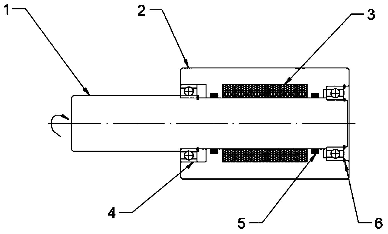
[0032] like figure 2 , the present invention proposes a radio frequency rotary joint for an ion etching system, including a radio frequency rotor 1 for accessing a bias electrode 19 and a radio frequency stator 2 for accessing a radio frequency current, and the radio frequency stator 2 is provided with Rotating hole; the radio frequency rotor 1 can be rotatably placed in the rotating hole; a conductive jacket 3 made of spherical metal particles is embedded between the inner wall of the rotating hole and the outer wall of the radio frequency rotor 1, and the spherical metal particles preferably adopt the conductivity coefficient Excellent copper.

[0033] The spherical metal particles of the conductive jacket 3 are closely arranged one by one, so the conductive jacket 3 enables the RF rotor 1 to rotate smoothly in the rotating hole of the RF stator 2, and at the same time makes the gap between the RF rotor 1 and the RF stator 2 rotate Maintain reliable electrical contact, thi...


PUM


Abstract

The invention discloses a radio-frequency rotary joint and an ion etching system therewith. The radio-frequency rotary joint comprises a radio-frequency rotor used for accessing a bias electrode and a radio-frequency stator used for accessing a radio-frequency current, and a rotating hole is formed in the radio-frequency stator; the radio-frequency rotor is rotatably arranged in the rotating hole; and a conductive jacket formed by spherical metal particles is embedded between the inner wall of the rotating hole and the outer wall of the radio-frequency rotor. According to the invention, through the conductive jacket which is formed by the spherical metal particles and arranged between the radio-frequency stator and the radio-frequency rotor, effective connection of the radio-frequency current between the rotary joint and the bias electrode is ensured, the smooth rotation of the radio-frequency rotor in the radio-frequency stator can also be ensured, the rotating requirement of the substrate after being connected with the rotary joint is met, and the speed and uniformity of coating and etching of the ion etching system are improved. The ion etching system is connected with a rotating platform, the substrate and the radio-frequency rotor through a dynamic sealing device, and meanwhile, the vacuum sealing requirement of the cavity etching is met.

Description

technical field [0001] The invention belongs to the technical field of semiconductor etching, and in particular relates to a radio frequency rotary joint and an ion etching system provided with the radio frequency rotary joint. Background technique [0002] In semiconductor equipment, electrical and fluid connections between the rotating part and the support often exist, and when the rotating part rotates on the support, these connections may undesirably wrap around itself, the rotating part, the support or the device Torsion or twisting in other mechanisms that may prevent continuous rotation of the rotating member in one direction, so here a swivel joint is required so that the electrical or fluid inlet port does not rotate with the rotating member. [0003] Conventional ion beam etching processes typically involve tilting and rotating the substrate during etching. In conventional approaches, substrate tilt is used to control the angle of incidence of ions striking the su...

Claims


Application Information

Patent Timeline
Patent Type & Authority Applications(China)
IPC IPC(8): H01J37/32
CPCH01J37/32431H01J37/32798H01J37/32807H01J2237/3174
Inventor 刘海洋邱勇刘小波李娜程实然王铖熠胡冬冬许开东
Owner JIANGSU LEUVEN INSTR CO LTD
Why Eureka
Try Eureka