An early air cut-off device for gear shift assist system

A power-assisting system and air-cutting technology, which is applied in transmission control, components with teeth, belts/chains/gears, etc., can solve the problems of affecting the performance and life of the synchronizer, precise control of the timing of the end of the lack of assistance, and achieve a simple structure. , strong practicability and sensitive action

Active Publication Date: 2020-08-04
BEIJING INST OF SPACE LAUNCH TECH +1
View PDF11 Cites 0 Cited by
  • Summary
  • Abstract
  • Description
  • Claims
  • Application Information

AI Technical Summary

Problems solved by technology

Although this method solves the problem of timing when the power assist is turned on, the timing of ending the power assist is when the clutch is engaged.
In the process of shifting gears, only a large shifting force is required during the synchronization process of the synchronizer. After the synchronization process of the synchronizer is completed, if the shift power has not ended before the gear sleeve of the synchronizer and the ring gear mesh, it will be in the synchronization process. The collision and secondary impact between the locking surfaces during the meshing process between the gear sleeve and the ring gear will also affect the performance and life of the synchronizer
And at present, there is no technology in the art to precisely control the timing of the power assist end of the shift assist system

Method used


Image

  • An early air cut-off device for gear shift assist system
  • An early air cut-off device for gear shift assist system
  • An early air cut-off device for gear shift assist system

Examples


Embodiment Construction

[0019] First of all, it needs to be explained that the orientation words such as up, down, left, right, front, and back described in the present invention are only described according to the accompanying drawings, so as to facilitate understanding, and are not intended to limit the technical solution and scope of protection of the present invention. .

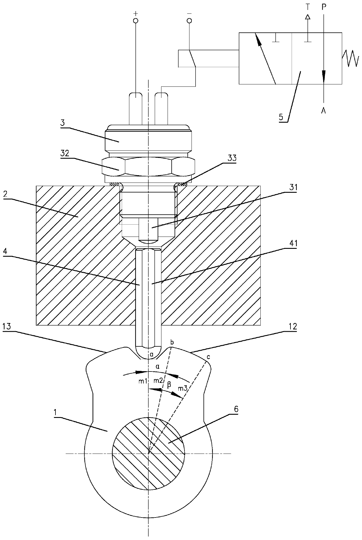
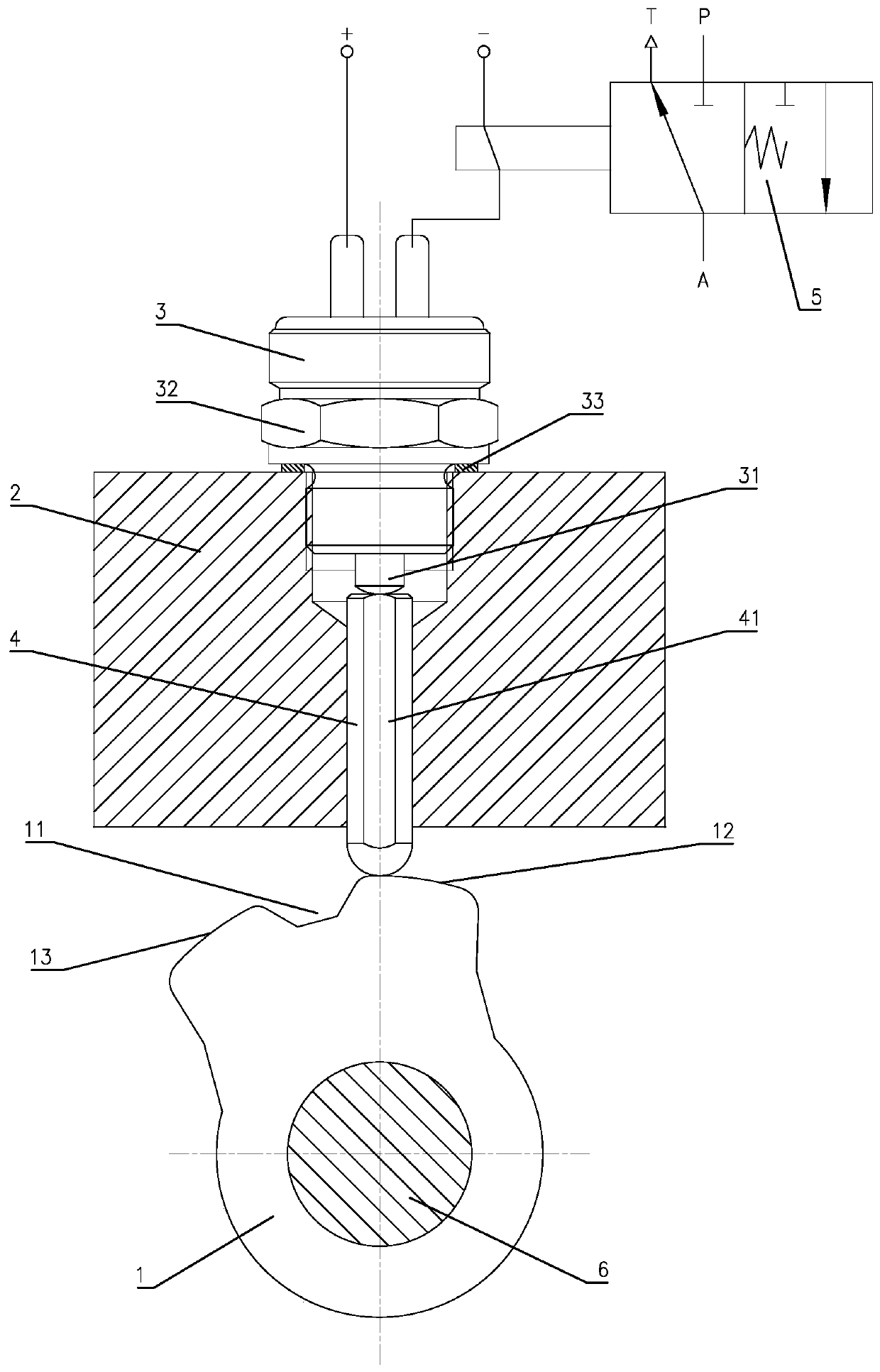
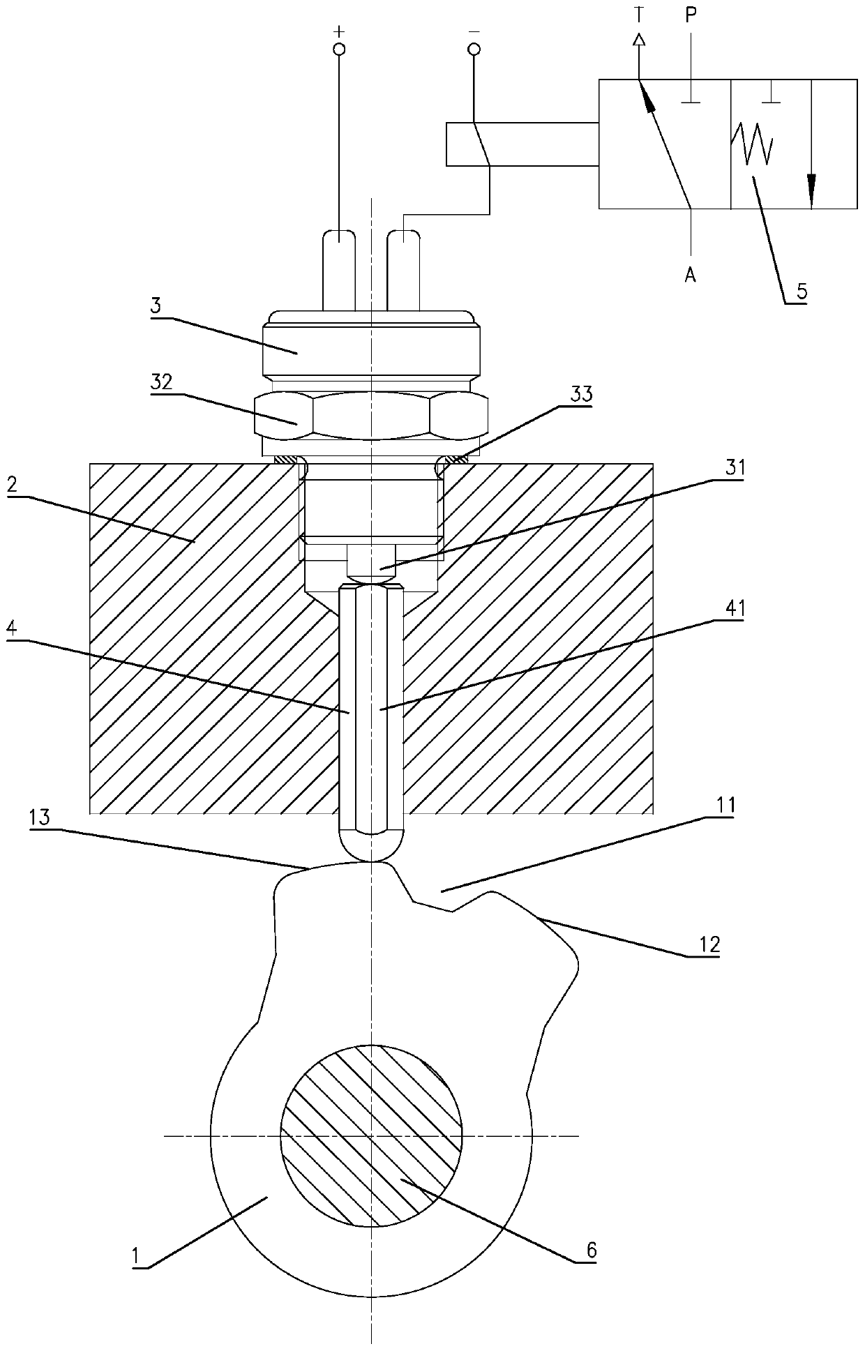
[0020] Such as Figure 1 to Figure 3 Shown is a specific embodiment of an early air cut-off device for a shift assist system of the present invention, including a shift trigger block 1 , a fixed seat 2 , a trigger switch 3 , a trigger push rod 4 and an electromagnetic control valve 5 . Fix the shift trigger block 1 on the shift shaft 6 of the gearbox, and set a neutral gear groove 11 on the top of the shift trigger block 1 with a notch width greater than the groove bottom width, and on both sides of the neutral gear groove 11 Correspondingly set the front shifting arc-shaped protrusion 12 and the rear shifting arc-shaped protr...


PUM


Abstract

The invention relates to an in-advance gas cut-off device used for gear-shifting power-assisted system. The system comprises a gear-shifting trigger block, a fixing base, a trigger switch, a trigger ejector rod and an electromagnetic control valve, wherein the gear-shifting trigger block is fixed to a gear-shifting shaft, and a neutral position groove is formed in the top of the gear-shifting trigger block. The two sides of the neutral position groove are correspondingly provided with a front gear engaging arc protrusion and a rear gear engaging arc protrusion. The fixing base is fixed to theupper side of the gear-shifting trigger block, the trigger switch is fixed to the fixing base, and the trigger ejector rod is arranged in a guide hole of the fixing base. The upper end of the triggerejector rod is located on the lower side of a contact pin of the trigger switch, and the lower end of the trigger ejector rod is located in the neutral position groove. The electromagnetic control valve is a normally-open two-position three-way electromagnetic valve, and the electromagnetic control valve and the trigger switch are connected in series between the positive and negative electrodes ofa vehicle power supply. A gas inlet P of the electromagnetic control valve is connected with a gas source, a gas outlet A is connected with the gear-shifting power-assisted system, and an exhaust port T communicates with the atmosphere. The system has the advantages of being simple in structure, low in cost, sensitive in action, high in accuracy and high in practicability.

Description

technical field [0001] The invention relates to a gear shift assist system, in particular to an early air cut-off device for the gear shift assist system. Background technique [0002] With the development of vehicle technology, people's requirements for driving comfort are getting higher and higher. The ease of shifting gears is an important indicator for evaluating driving comfort. For heavy-duty vehicles, the shifting mechanism is heavy when shifting gears, requires a large shifting force, and the driver's labor intensity has attracted more and more attention from the industry. At present, synchronizers are usually used in this field to solve the phenomenon of impact and tooth hitting during gear shifting, and the gear shifting force is reduced by adding a gear shift assist system to improve the portability of gear shifting. The gearboxes of heavy-duty vehicles mostly use air-operated high-low gear switching sub-boxes, and the gearbox shift assist system generally adopt...

Claims


Application Information

Patent Timeline
Patent Type & Authority Patents(China)
IPC IPC(8): F16H61/30
CPCF16H61/30F16H2061/301
Inventor 赵一民张磊张斌单红波李洪彪张顺柳春旺高丽丽王忠吴学雷刘懿敏胡习明赵焱明苏辛胡文俊王旭赵敬民杨必武赵民江思荣
Owner BEIJING INST OF SPACE LAUNCH TECH
Why Eureka
Try Eureka