Airglow imaging interferometer for detecting upper atmospheric temperature and volume emission rate in automatic remote sensing mode

A technology of atmospheric temperature and imaging interference, applied in the direction of instruments, measuring devices, etc., can solve problems such as the inability to measure high-level atmospheric temperature and volume emissivity parameters, achieve good practical value, save costs, and improve measurement accuracy

Inactive Publication Date: 2019-08-06
XIAN UNIV OF TECH
View PDF10 Cites 2 Cited by
  • Summary
  • Abstract
  • Description
  • Claims
  • Application Information

AI Technical Summary

Problems solved by technology

[0006] The purpose of the present invention is to provide an airglow imaging interferometer for automatic remote sensing detection of high-level atmospheric temperature and volume emissivity, which solves the problem that the existing high-level atmospheric temperature and volume emissivity parameters cannot be measured

Method used


Image

  • Airglow imaging interferometer for detecting upper atmospheric temperature and volume emission rate in automatic remote sensing mode
  • Airglow imaging interferometer for detecting upper atmospheric temperature and volume emission rate in automatic remote sensing mode
  • Airglow imaging interferometer for detecting upper atmospheric temperature and volume emission rate in automatic remote sensing mode

Examples


Embodiment Construction

[0021] The present invention will be described in detail below in conjunction with the accompanying drawings and specific embodiments.

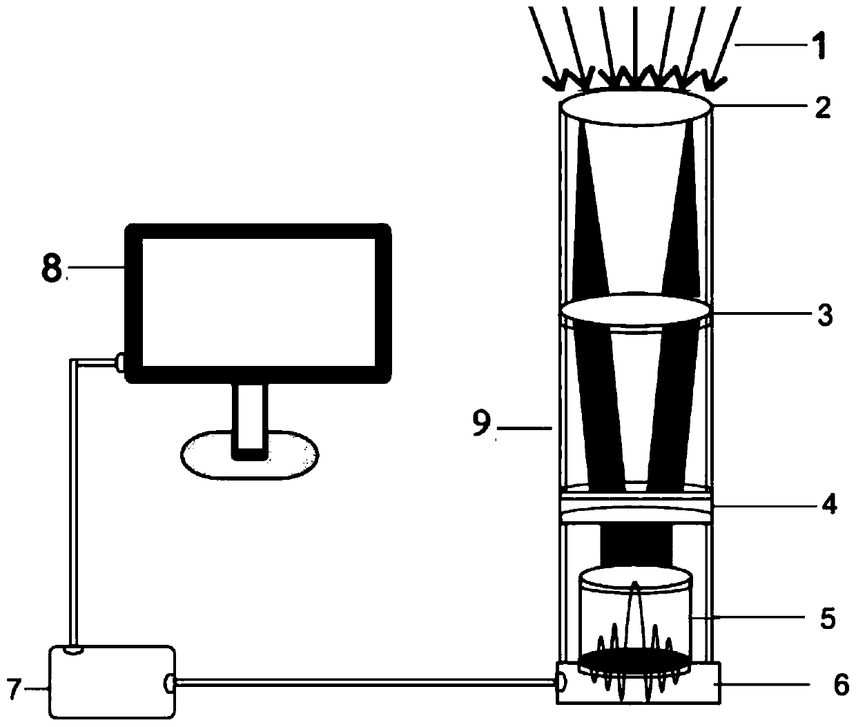
[0022] The airglow imaging interferometer for automatic remote sensing detection of high-level atmospheric temperature and volume emissivity of the present invention, such as figure 1 As shown, it includes a tubular lens barrel 9, and the inner wall of the lens barrel 9 is sequentially provided with an imaging lens 5 of an entrance diaphragm 2, a convex lens 3, a filter 4 and a CCD detector 6 from top to bottom, and the CCD detector 6 passes through the data line in turn. Connect the I\O interface of Raspberry Pi 7 and computer 8.

[0023] The convex lens 3 and the filter 4 filter and screen the light of the fixed airglow band, use the CCD detector 6 to obtain the image of the target light source, connect to the Raspberry Pi 7 and transmit the obtained image to the computer 8, and the computer 8 analyzes the data and displays it on On the se...


PUM


Abstract

The invention discloses an airglow imaging interferometer for detecting an upper atmospheric temperature and a volume emission rate in an automatic remote sensing mode. The airglow imaging interferometer comprises a tubular lens barrel, wherein the inner wall of the lens barrel is sequentially provided with an incident pupil, a convex lens, an optical filter and an imaging lens of a CCD detector from top to bottom, wherein the CCD detector is sequentially connected with an I\O interface of a Raspberry Pi and the computer by means of data lines. The airglow imaging interferometer adopts the optical filter for screening different diatomic and polyatomic airglow target light sources based on an FPI interference optical filter and the principle of ''rotational line temperature measurement method'', adopts the CCD detector for carrying out image acquisition on interferometric fringes formed by airglow, controls the CCD detector remotely and realizes information transmission by utilizing a Raspberry Pi third-generation B+ type, and performs data analysis and displays a result on the computer; and the airglow imaging interferometer has no moving parts, improve the measurement precision and saves the cost.

Description

technical field [0001] The invention belongs to the technical field of remote sensing detection equipment, in particular to an airglow imaging interferometer for automatic remote sensing detection of high-level atmospheric temperature and volume emissivity. Background technique [0002] The atmospheric concentration in the middle and upper atmosphere (80-300km) is very low, its temperature changes greatly, and there are few means of detection of the upper atmosphere, resulting in the detection of the temperature of the middle and upper atmosphere becoming very slow in the past 30 years. The instruments for detecting parameters such as wind speed and temperature in the upper atmosphere include spaceborne and ground-based instruments and equipment. In 1991, the wind imaging interferometer WINDII (Wind Imaging Interferometer) and the high-resolution Doppler imager HRDI (High-Resolution Doppler Imager) carried on the upper atmospheric research satellite UARS (Upper Atmospheric R...

Claims


Application Information

Patent Timeline
IPC IPC(8): G01D21/02
CPCG01D21/02
Inventor 唐远河董晨孙鹏家敏郭栋森乔良
Owner XIAN UNIV OF TECH
Why Eureka
Try Eureka