
Weighing device and horizontal type cement bin

A weighing device and mounting plate technology, which is applied in the direction of measuring devices, detailed information of weighing equipment, weighing, etc., can solve the problems of damage to the load cell, poor use effect, heavy weight, etc., and achieve high safety , Simple structure, good stability

Pending Publication Date: 2019-08-06
SINOHYDRO FOUND ENG
View PDF0 Cites 0 Cited by
  • Summary
  • Abstract
  • Description
  • Claims
  • Application Information

AI Technical Summary

Problems solved by technology

Due to the large volume and heavy weight of the horizontal cement silo, the existing load cell is easily damaged during transportation and use, and the use effect is not good

Method used


Image

  • Weighing device and horizontal type cement bin
  • Weighing device and horizontal type cement bin
  • Weighing device and horizontal type cement bin

Examples


Embodiment 1

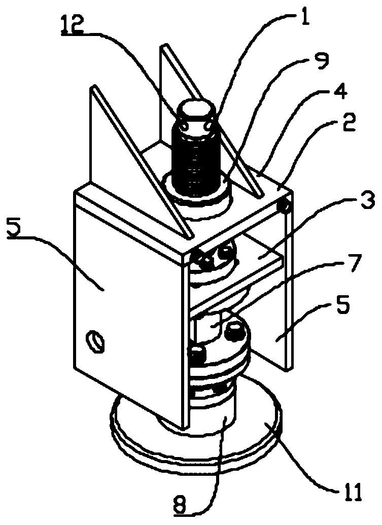
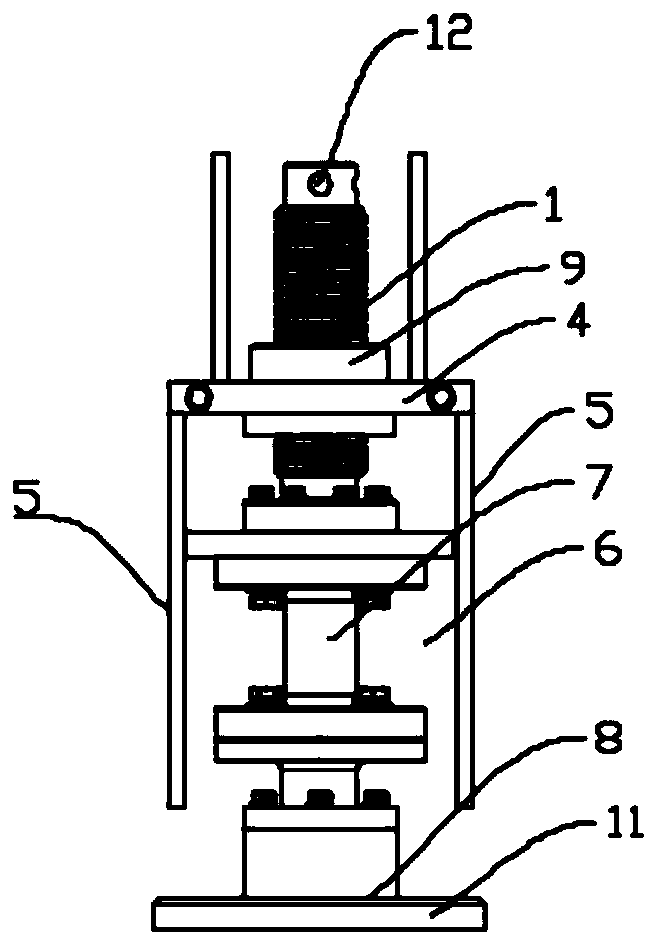
[0038] Such as figure 1 , figure 2 As shown, this embodiment provides a weighing device, including a telescopic structure and a tension and compression sensor 7. The telescopic structure includes a screw rod 1, a fixing base 2 and a screw base 3. The fixing base 2 includes a mounting plate 4 and a symmetrical installation The limit support plate 5 at both ends of the plate 4, the limit support plate 5 is perpendicular to the mounting plate 4, the area between the limit support plates 5 is the limit zone 6, the screw rod 1 is threaded with the mounting plate 4, and the screw rod 1 is located One end of the limit zone 6 rotates and fits with the screw base 3 through a bearing. The screw base 3 is located in the limit zone 6 and both ends of the screw base 3 slidably cooperate with the limit support plate 5, and the tension and compression sensor 7 is fixed on The lower end of the screw base 3.

[0039] Specifically, the fixing base 2 is fixedly installed at the lower end of the eq...

Embodiment 2

[0044] This embodiment is optimized and defined on the basis of the foregoing embodiment 1.

[0045] It also includes a sensor base 8 fixed on the lower end of the tension and compression sensor 7, and the sensor base 8 is fixedly connected to the tension and compression sensor 7 by bolts.

[0046] The sensor base 8 is designed to avoid direct contact between the tension and compression sensor 7 and the supporting surface, and can protect the tension and compression sensor 7 from collisions, thereby achieving high safety and good stability.

Embodiment 3

[0048] This embodiment is optimized and defined on the basis of the foregoing embodiment 2.

[0049] In order to facilitate the installation of the screw rod 1, a nut 9 is provided in the middle of the mounting plate 4. The screw rod 1 and the nut 9 are threadedly matched, and the axes of the screw rod 1, the tension and compression sensor 7 and the sensor base 8 are consistent.


PUM


Abstract

The invention belongs to the technical field of weighing devices and discloses a weighing device and a horizontal type cement bin. The weighing device includes a telescopic structure and a tension andcompression sensor; the telescopic structure comprises a screw rod, a fixing seat and a screw rod base; the fixing base comprises a mounting plate and limiting supporting plates symmetrically arranged at two ends of the mounting plate; an area between the limiting supporting plates is a limiting area; the screw rod is in threaded connection with the mounting plate; one end of the screw rod, whichis located in the limiting area, is rotationally matched with the screw rod base; the screw rod base is located in the limiting area; two ends of the screw rod base are respectively in sliding fit with the limiting supporting plates; and the tension and compression sensor is fixed at the lower end of the screw rod base. The weighing device provided by the invention is simple and compact in structure. Modular design is adopted, so that rapid installation is realized; any functions of original equipment are not influenced;and the weighing device is safe and stable, can be installed in a modular mode, and can be rapidly installed on equipment needing weighing.

Description

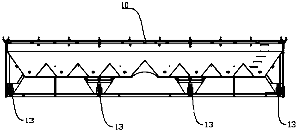
Technical field [0001] The invention relates to the technical field of weighing devices, in particular to a weighing device and a horizontal cement silo. Background technique [0002] The market has put forward higher demands for the convenience, versatility and system integration of traditional equipment. Traditional equipment often has a single function and can no longer fully meet the needs of modern production. During our investigation, we found that the existing load cell has developed greatly and can satisfy various occasions. However, the design of weighing devices is still very few, especially weighing devices with simple structure, convenient installation, safe use and good stability. Combined with the company's existing product horizontal cement silo, due to construction requirements, it is urgent to install a reliable and convenient weighing device. Due to the large volume and heavy weight of the horizontal cement silo, the currently installed load cell is easily da...

Claims


Application Information

Patent Timeline
Patent Type & Authority Applications(China)
IPC IPC(8): G01G19/00G01G21/00B65D90/48
CPCG01G19/00G01G21/00B65D90/48
Inventor 郭万红王保辉杨振中孙仲彬张裕文杜晓麟杨雨赵峥
Owner SINOHYDRO FOUND ENG
Learn More