Real-time identification method and system for dominant oscillation mode of electric power system under fault disturbance
A power system and fault disturbance technology, applied to electrical components, circuit devices, AC network circuits, etc., can solve problems such as large amount of calculation, inability to accurately identify the dominant mode of system oscillation, and increase in the order of the coefficient matrix to achieve output Signal and can be customized, the output signal is rich, the effect of strong modeling ability
- Summary
- Abstract
- Description
- Claims
- Application Information
AI Technical Summary
Problems solved by technology
Method used
Image
Examples
Embodiment 1
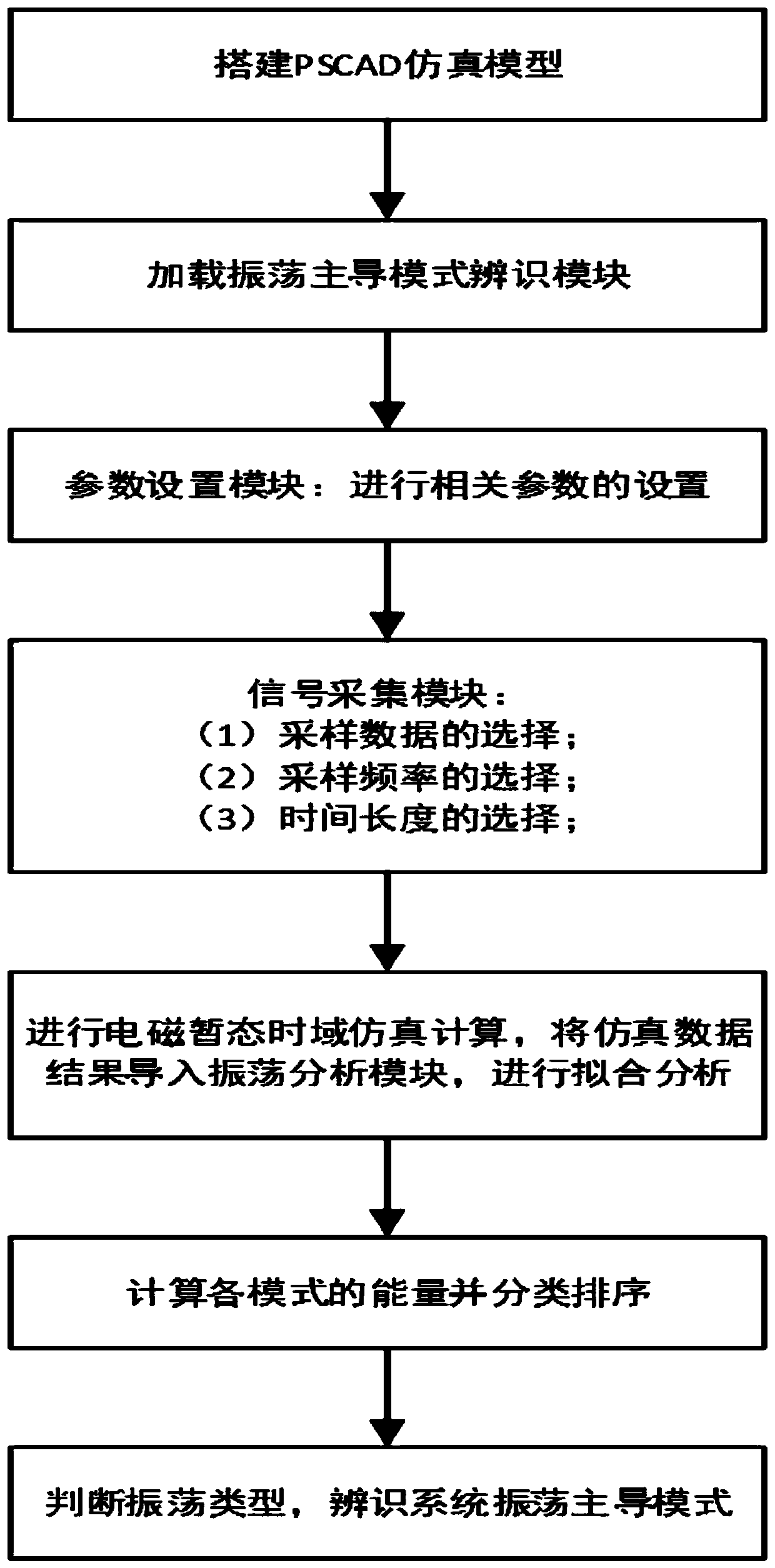
[0065] see figure 1 , a method for real-time identification of the dominant mode of power system oscillation under fault disturbance according to an embodiment of the present invention, the specific steps are as follows:
[0066] Step 1: Build a time-domain simulation model of the power system based on electromagnetic transient simulation software
[0067] Step 2: Load the oscillation dominant mode identification module, and connect and combine the established internal modules and component models according to the link information of the modules.
[0068] Step 3: Set parameters such as total simulation time, simulation step size, step size for reading simulation result data, system operation mode, fault disturbance mode, analyzed oscillation signal and analysis result output.
[0069] Step 4: Select the sampling data, sampling frequency and length of time for analysis.
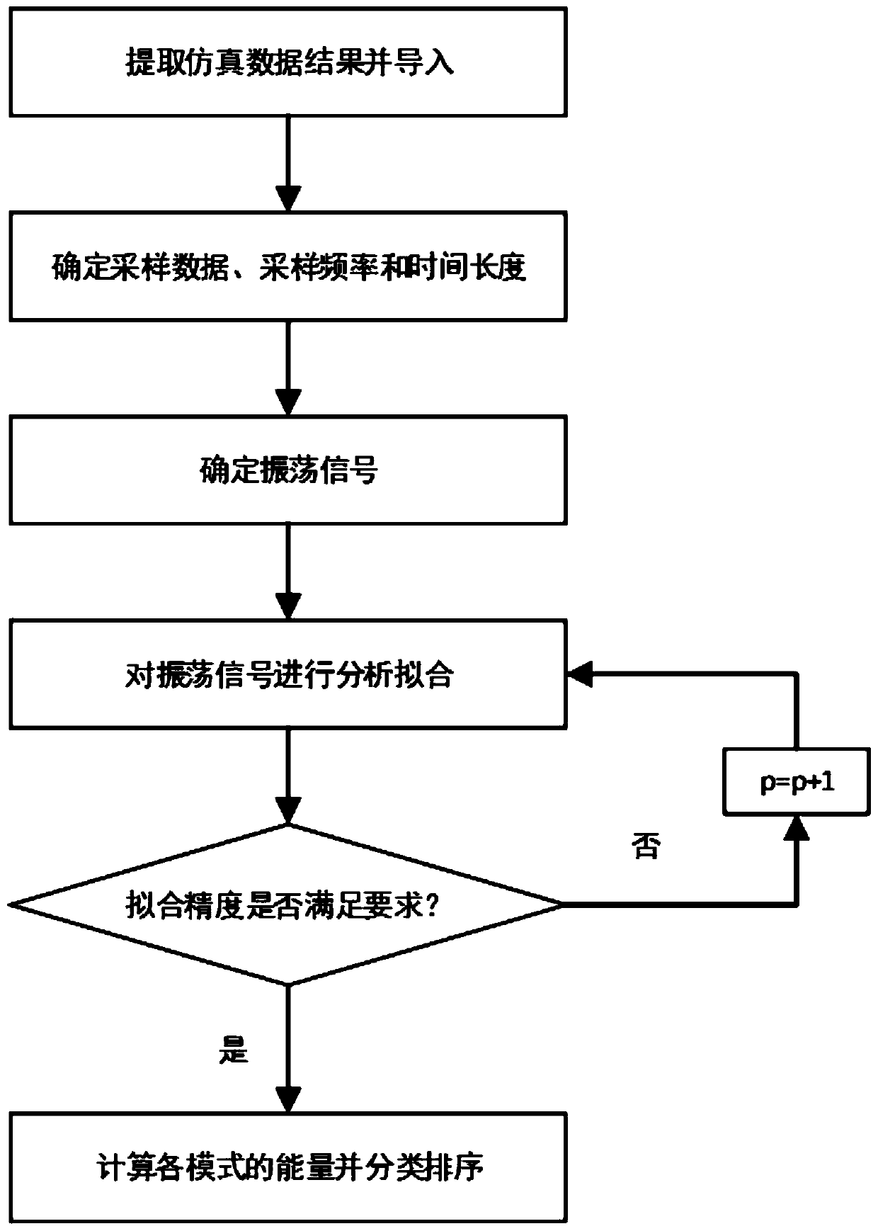
[0070] Step 5: Perform electromagnetic transient time-domain simulation calculations, and import the simu...
Embodiment 2
[0075] see Figure 1 to Figure 5 , Embodiment 2 takes the IEEE first standard model (single machine infinite system) containing series capacitor compensation as an example to introduce the identification method of the oscillation dominant mode of the present invention, specifically comprising:
[0076] Step 1: Build a time domain simulation model based on PSCAD / EMTDC.
[0077] Step 2: Load the oscillation dominant mode identification module, and connect and combine the established internal modules and component models according to the link information of the modules.
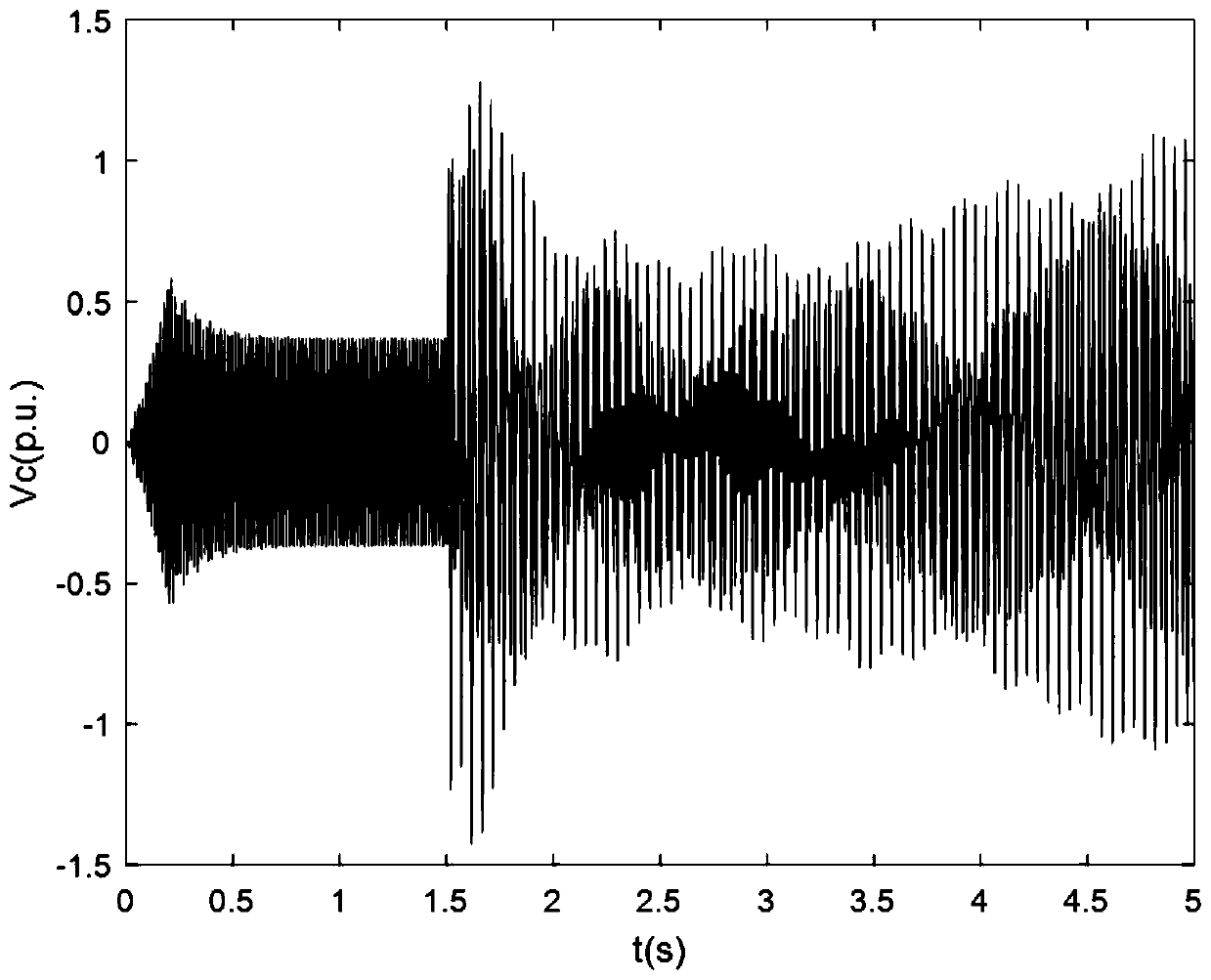
[0078] Step 3: Set the total simulation time to 5s, the simulation step to 100us, the step to read the simulation result data to 1000us, and the system operation mode to X c =0.371p.u., the fault disturbance mode is a three-phase short circuit at the equivalent power supply through the transition impedance at 1.5s, the fault duration is 0.075s, and the analyzed oscillation signal is the voltage of the system se...
PUM
 Abstract
Description
Claims
Application Information
 - R&D
- Intellectual Property
- Life Sciences
- Materials
- Tech Scout
- Unparalleled Data Quality
- Higher Quality Content
- 60% Fewer Hallucinations
Browse by: Latest US Patents, China's latest patents, Technical Efficacy Thesaurus, Application Domain, Technology Topic, Popular Technical Reports.
© 2025 PatSnap. All rights reserved.Legal|Privacy policy|Modern Slavery Act Transparency Statement|Sitemap|About US| Contact US: help@patsnap.com


