Inner hole gluing machine

A glue coating machine and inner hole technology, which is applied in the coating, the device for coating liquid on the surface, the pretreatment surface, etc., can solve the problems of the large space occupied by the glue, the difficulty of cleaning the fixture, and the difficulty of equipment maintenance, etc. To achieve the effect of fast heating, reduce unclean pipes, and increase the difficulty of cleaning

Pending Publication Date: 2019-08-09
SUZHOU ANGEM PRECISION MACHINE
View PDF0 Cites 2 Cited by
  • Summary
  • Abstract
  • Description
  • Claims
  • Application Information

AI Technical Summary

Problems solved by technology

[0003] Traditional manual painting technology: high labor cost, uneven glue application, strong paint smell, large employee turnover, low glue application efficiency, and large space occupied by glue application (employee work area, drying equipment area, product storage area); and Existing automatic spraying equipment has the following disadvantages:
[0004] 1. High production efficiency, but low glue utilization rate (30%-60%);
[0005] 2. The spraying dust is large, which needs to be discharged by auxiliary pipelines, and dust treatment should be carried out externally; (not environmentally friendly)
[0006] 3. Products of different specifications require fixtures of different specifications (the fixtures take up space), and it is difficult to clean the fixtures;
[0007] 4. The spray gun is easy to block the gun and needs to be cleaned frequently, making it difficult to maintain the equipment

Method used


Image

  • Inner hole gluing machine
  • Inner hole gluing machine
  • Inner hole gluing machine

Examples


Embodiment Construction

[0043] The technical solutions in the embodiments of the present invention will be clearly and completely described below in conjunction with the accompanying drawings in the embodiments of the present invention. Obviously, the described embodiments are only some embodiments of the present invention, not all embodiments. Based on the embodiments of the present invention, all other embodiments obtained by persons of ordinary skill in the art without making creative efforts belong to the protection scope of the present invention.

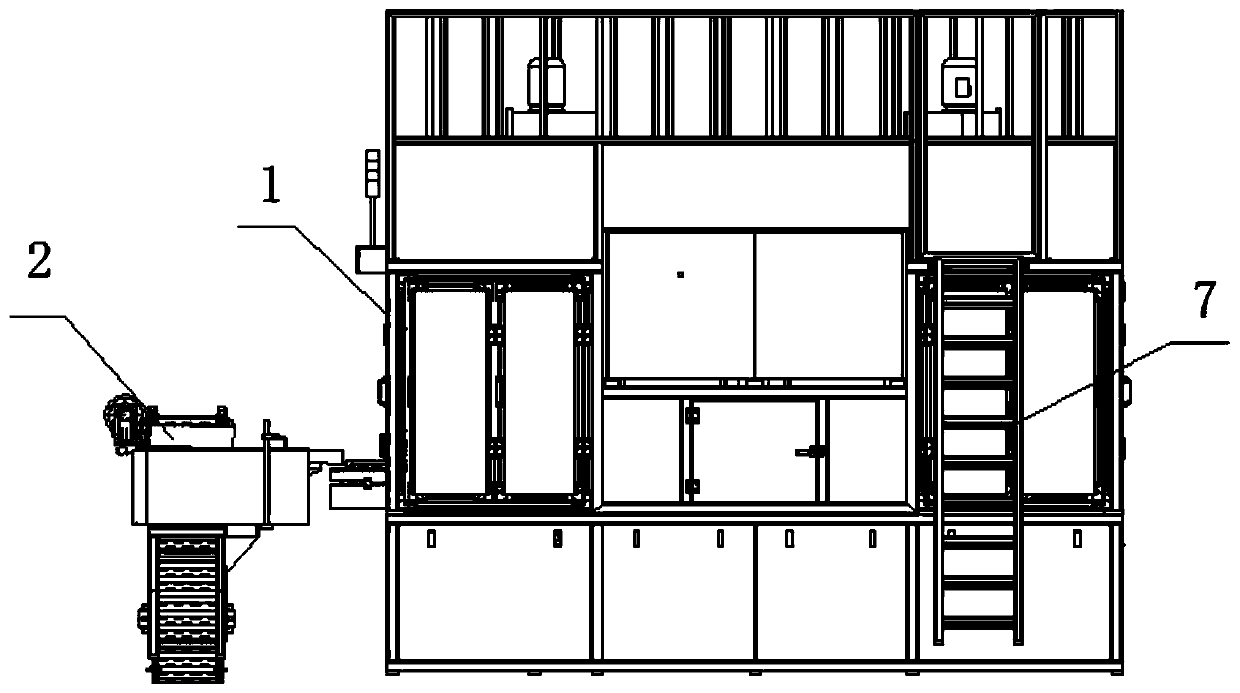
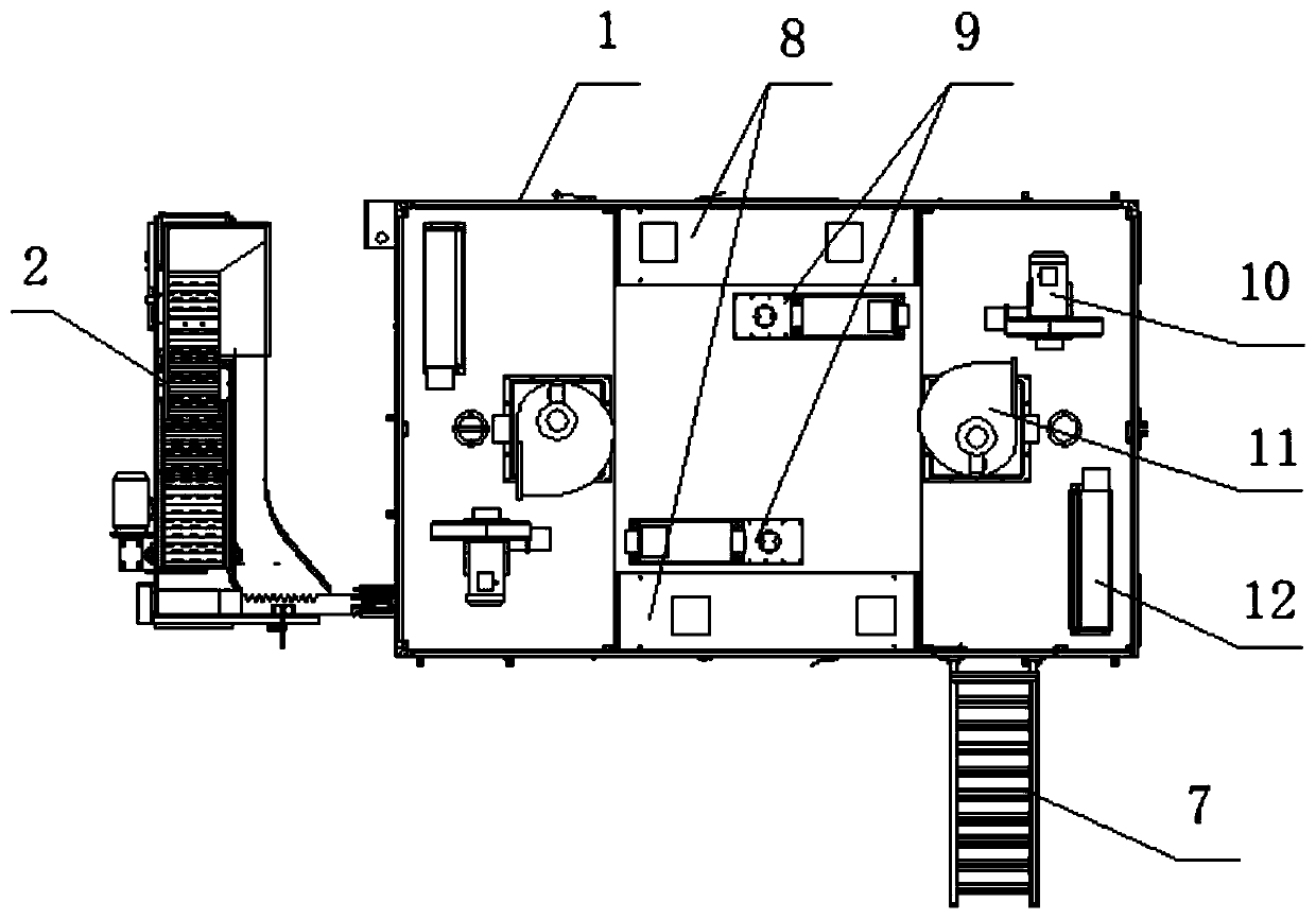
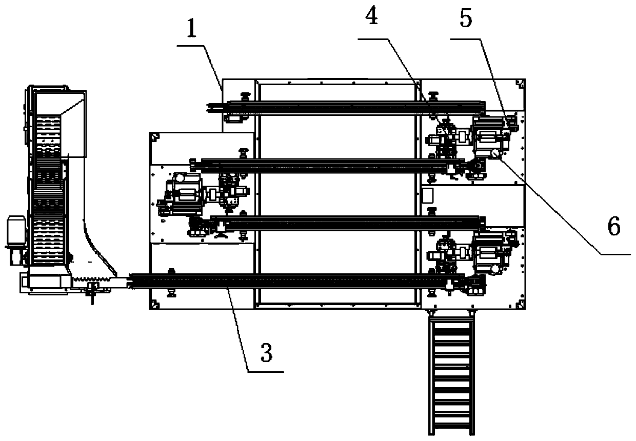
[0044] see Figure 1-15 , in the embodiment of the present invention, a kind of inner hole gluing machine comprises frame 1, and the side of frame 1 is provided with feeding conveying line 2, is used for conveying the product to the feeding end of chain feeding mechanism 3, and frame 1 A chain feeding mechanism 3 and a shifting and grabbing mechanism 13 are installed horizontally in the middle. The chain feeding mechanism 3 is used for horizontally conv...


PUM


Abstract

The invention discloses an inner hole gluing machine. The machine comprises a rack, wherein a feeding conveying line is arranged beside the rack, a chain feeding mechanism and a moving and grabbing mechanism are transversely arranged in the middle of the rack, a positioning mechanism is arranged at one end of the chain feeding mechanism, a glue rolling assembly and a rotary gluing part are arranged on the parts, beside the positioning mechanism, of the rack, one side of the rotary gluing part is connected with a glue supply system, an electric heater and an exhaust fan are arranged on the upper part of the rack, the electric heater communicates with one side of the glue rolling assembly through an air conveying pipe, and a PLC control cabinet is arranged on one side of the rack, and the feeding conveying line, the chain feeding mechanism, the positioning mechanism, the rotary gluing part, the moving and grabbing mechanism and the glue supply system are all electrically connected with the PLC control cabinet. The inner hole gluing machine has the advantages that automatic spraying treatment can be carried out on inner hole parts, the automation degree is improved, the working intensity is reduced, and the working efficiency is improved.

Description

technical field [0001] The invention relates to the technical field of roller spraying equipment, in particular to an inner hole gluing machine. Background technique [0002] In the shock absorption system of the vehicle, the bushing cooperates with the shock absorber to play the role of shock absorption. The use of the bush can reduce the wear, vibration and noise of the equipment, and has the effect of anti-corrosion. The use of the bushing can also facilitate the maintenance of mechanical equipment and simplify the structure and manufacturing process of the equipment. The role of the bush in actual work has a lot to do with its application environment and purpose. The main considerations in the selection of the bushing are the pressure, velocity, pressure-velocity product and load nature that the bushing needs to bear. In addition, whether the bushing is lubricated and the state of the lubrication also determines its service effect and life. During the production proce...

Claims


Application Information

Patent Timeline
Patent Type & Authority Applications(China)
IPC IPC(8): B05C1/02B05C9/06B05C9/14B05C11/10B05C11/11B05C13/02B05D3/04
CPCB05C1/022B05C9/06B05C9/14B05C11/10B05C11/11B05C13/02B05D3/0413
Inventor 卢茂盛
Owner SUZHOU ANGEM PRECISION MACHINE
Why Eureka
Try Eureka