Mirror surface cleaning device of monitoring camera

A technology for monitoring cameras and cleaning devices, applied in the field of camera cleaning, can solve the problems of poor mirror cleaning effect and the inability of brushes to maintain the fit effect, etc., and achieve the effect of mirror cleaning and high efficiency

Inactive Publication Date: 2019-08-09
抚州市东乡区东红光学科技有限公司
View PDF8 Cites 11 Cited by
  • Summary
  • Abstract
  • Description
  • Claims
  • Application Information

AI Technical Summary

Problems solved by technology

The device only drives the brush to rotate through the motor to clean the camera, but the brush cannot maintain the bonding effect with the camera mirror, resulting in poor cleaning effect of the mirror. For this reason, a monitoring camera mirror cleaning device is now provided. Solve the above technical problems

Method used


Image

  • Mirror surface cleaning device of monitoring camera
  • Mirror surface cleaning device of monitoring camera
  • Mirror surface cleaning device of monitoring camera

Examples


Embodiment 1

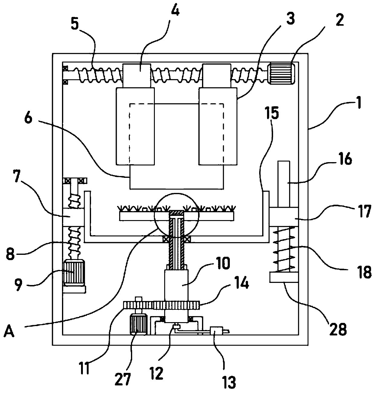
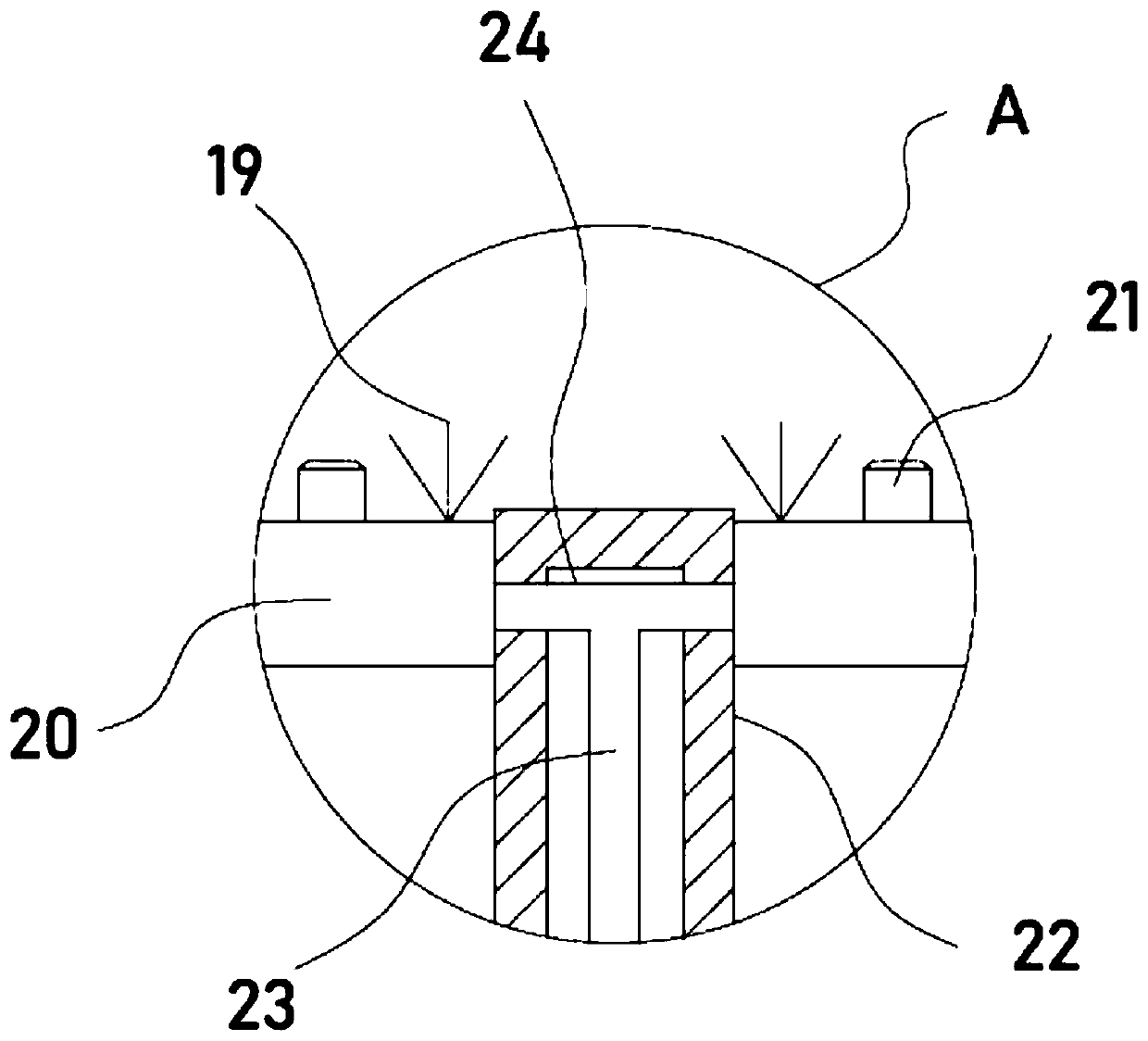
[0023] see Figure 1-5 , a monitoring camera mirror cleaning device, comprising a housing 1, the housing 1 is provided with a water tank 15 driven and connected by a lifting mechanism, the center of the water tank 15 is sealed and pivotally connected with a telescopic tube 22, and the upper side wall of the telescopic tube 22 is fixedly installed with symmetrical Two cleaning components are provided, and the clamping component for clamping the camera 6 is provided directly above the cleaning component through the transmission connection of the adjustment mechanism. 22 is extended with a water delivery main pipe 23 connected to an external water source, and the water delivery main pipe 23 is connected with several upwardly arranged nozzles 21 .

[0024] When cleaning the mirror surface of the camera 6, the camera 6 is clamped and fixed by the clamping assembly, one end of the mirror surface of the camera 6 is vertically downward, and the rotation of the telescopic tube 22 is re...

Embodiment 2

[0028] In order to improve the full cleaning effect of the device on the mirror surface of the camera 6, on the basis of Embodiment 1, the rotating mechanism includes a servo motor III27, and the output shaft of the servo motor III27 is driven to connect the outer surface and is sleeved with a drive sleeve fixed with a pinion gear 14. 10. The inner wall of the transmission sleeve 10 is axially provided with a card slot 26 , and the side wall of the telescopic tube 22 is fixed with a card bar 25 which slides and engages with the card slot 26 .

[0029] Through the above settings, the servo motor III27 is used to drive the main gear 11 to rotate, and the main gear 11 drives the pinion gear 14 meshed with it to rotate. At this time, the pinion gear 14 drives the transmission sleeve 10 to rotate, and the clip bar 25 is engaged with the clip slot 26. , to realize that the telescopic tube 22 drives the rotating plate 20 to rotate, and then realizes the rotating cleaning effect of the...


PUM


Abstract

The invention discloses a mirror surface cleaning device of a monitoring camera, and relates to the technical field of camera cleaning. The mirror surface cleaning device of the monitoring camera comprises a casing. Telescopic tubes are connected to the center of a water tank in sealed and pivoted modes. Two cleaning assemblies which are symmetrically arranged are fixedly installed on the upper side walls of the telescopic tubes. Clamping assemblies for clamping the camera is arranged right above the cleaning assemblies, and the clamping assemblies are connected in a transmission mode throughan adjustment mechanism. A water delivery main tube communicates with a plurality of spray heads arranged upwards. The mirror surface cleaning device of the monitoring camera can rotate through the cleaning assemblies driven by a rotating mechanism so that brushes rotatably clean the mirror surface of the camera; a lifting mechanism arranged can adjust the height of the cleaning assemblies so thatthe brushes can be closely attached to the mirror surface, sufficient pressing force during the mirror surface cleaning process is achieved, and the mirror surface cleaning of the camera is more efficient; and the spray heads arranged can spray cleaning liquid when the brushes rotatably clean, full wetting of the brushes is achieved, and the mirror surface can be fully and thoroughly cleaned.

Description

technical field [0001] The invention relates to the technical field of camera cleaning, in particular to a monitoring camera mirror cleaning device. Background technique [0002] Surveillance camera is a semiconductor imaging device, which has the advantages of high sensitivity, anti-glare, small distortion, small size, long life, and anti-vibration. In the surveillance camera security system, the image generation is mainly from the CCD camera at present, and the stored charge can also be taken out to change the voltage. It has the characteristics of anti-vibration and impact and is widely used. If the mirror surface of the surveillance camera is stained, it needs to be cleaned in time to ensure the light transmittance of the mirror surface. [0003] The patent with authorized notification number CN207222417U discloses a camera cleaning device, comprising: a hair brush, a motor, a motor chamber and a straight rod; the motor is arranged in the motor chamber, and the motor is...

Claims


Application Information

Patent Timeline
IPC IPC(8): B08B1/04B08B13/00
CPCB08B13/00B08B1/12B08B1/32
Inventor 游志强
Owner 抚州市东乡区东红光学科技有限公司
Why Eureka
Try Eureka