Textile yarn waxing device

A yarn and equipment technology, applied in the field of waxing equipment, can solve problems such as troublesome and low work efficiency, and achieve the effect of simple operation and improved work efficiency

Active Publication Date: 2019-08-09
绍兴柯桥瑞策纺织有限公司
View PDF5 Cites 8 Cited by
  • Summary
  • Abstract
  • Description
  • Claims
  • Application Information

AI Technical Summary

Problems solved by technology

[0003] In order to overcome the disadvantages of waxing by winding the yarn and rubbing the yarn against the wax block, which is cumbersome and has low work efficiency, the technical problem to be solved is to provide a spinning machine for textile use that is easy to operate and can improve work efficiency. Yarn waxing equipment

Method used


Image

  • Textile yarn waxing device
  • Textile yarn waxing device
  • Textile yarn waxing device

Examples


Embodiment 1

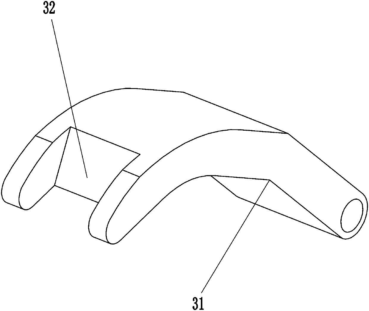
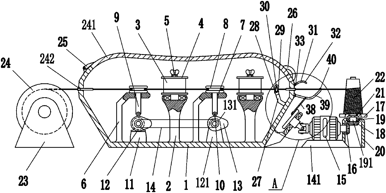
[0016] A kind of textile yarn waxing equipment, such as figure 1 As shown, it includes box body 1, support column 2, cylinder water-soluble wax 3, end cap 4, butterfly nut 5, L-shaped rod 6, sheave 8, ejector rod 9, small pulley 10, first support 11. Ordinary motor 12, support plate 121, cam 13, pulley 131, ordinary belt 14, trapezoidal plate 141, double-head drive motor 15, first bevel gear 16, first turntable 17, second bevel gear 18, deep Groove ball bearing 19, rotating shaft 191, protective shell 20, finished product reel 22, second support 23, raw material reel 24, shell 241, moldable hose 242, connection block 25 and handle 26, inside the box body 1 A support column 2 is fixedly connected in the middle of the bottom, and a support column 2 is also fixedly connected to the right side of the bottom of the box body 1. The box body 1 is connected to the support column 2 by means of bolt connection. Cylinder water soluble wax 3, the top of cylinder water soluble wax 3 is pr...

Embodiment 2

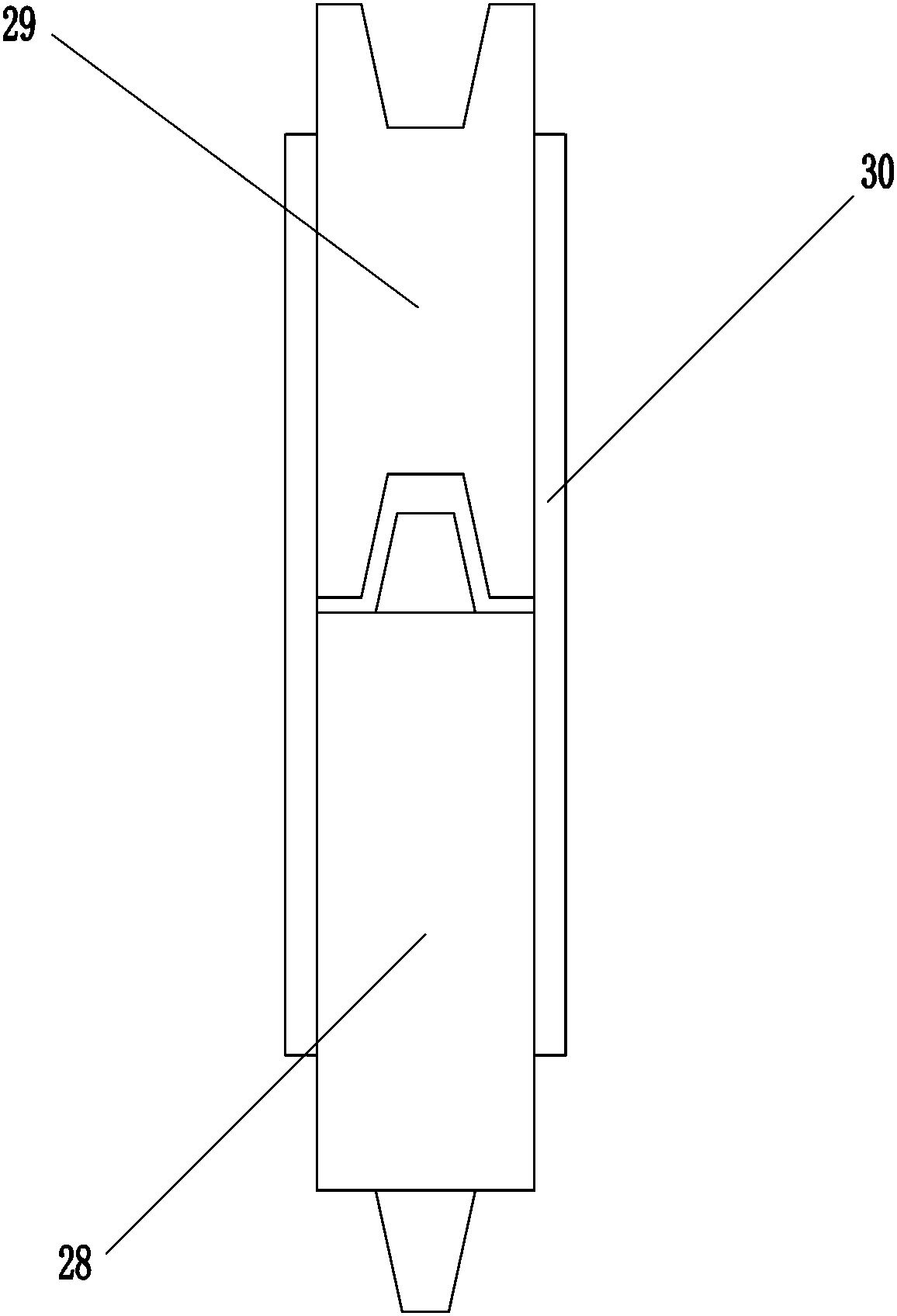
[0018] A kind of textile yarn waxing equipment, such as Figure 1-2As shown, it includes box body 1, support column 2, cylinder water-soluble wax 3, end cap 4, butterfly nut 5, L-shaped rod 6, sheave 8, ejector rod 9, small pulley 10, first support 11. Ordinary motor 12, support plate 121, cam 13, pulley 131, ordinary belt 14, trapezoidal plate 141, double-head drive motor 15, first bevel gear 16, first turntable 17, second bevel gear 18, deep Groove ball bearing 19, rotating shaft 191, protective shell 20, finished product reel 22, second support 23, raw material reel 24, shell 241, moldable hose 242, connection block 25 and handle 26, inside the box body 1 A support column 2 is fixedly connected to the middle of the bottom, and a support column 2 is also fixedly connected to the right side of the inner bottom of the box body 1. The tops of the two support columns 2 are rotatably installed with a cylinder of water-soluble wax 3, and the top of the cylinder of water-soluble wa...

Embodiment 3

[0021] A kind of textile yarn waxing equipment, such as Figure 1-4 As shown, it includes box body 1, support column 2, cylinder water-soluble wax 3, end cap 4, butterfly nut 5, L-shaped rod 6, sheave 8, ejector rod 9, small pulley 10, first support 11. Ordinary motor 12, support plate 121, cam 13, pulley 131, ordinary belt 14, trapezoidal plate 141, double-head drive motor 15, first bevel gear 16, first turntable 17, second bevel gear 18, deep Groove ball bearing 19, rotating shaft 191, protective shell 20, finished product reel 22, second support 23, raw material reel 24, shell 241, moldable hose 242, connection block 25 and handle 26, inside the box body 1 A support column 2 is fixedly connected to the middle of the bottom, and a support column 2 is also fixedly connected to the right side of the inner bottom of the box body 1. The tops of the two support columns 2 are rotatably installed with a cylinder of water-soluble wax 3, and the top of the cylinder of water-soluble w...


PUM


Abstract

The invention relates to waxing equipment, in particular to a textile yarn waxing device in order to achieve the technical effects of being easy to operate and capable of improving the working efficiency. According to the technical scheme, the textile yarn waxing device comprises a box, supporting columns, cylindrical water-soluble waxes, end covers, butterfly nuts, L-shaped rods, grooved pulleys,push rods, small pulleys, a first support, a common motor, a supporting plate and the like. One supporting column is fixedly connected to the middle of the bottom of the interior of the box. The other supporting column is fixedly connected to the right side of the bottom of the interior of the box. The top ends of the two supporting columns are both rotatably provided with the cylindrical water-soluble waxes. The end covers are arranged on the tops of the cylindrical water-soluble waxes. The butterfly nuts playing a fixing role are arranged on the end covers. According to the textile yarn waxing device, the common motor can rotate to drive a yarn to move up and down to prevent the yarn from repeatedly rubbing the same positions of the cylindrical water-soluble waxes. There is no need to replace the cylindrical water-soluble waxes frequently. Thus, the textile yarn waxing device is easier to operate. The rotating speed of a double-head driving motor is higher. Accordingly, the workingefficiency can be improved.

Description

technical field [0001] The invention relates to waxing equipment, in particular to a waxing equipment for textile yarns. Background technique [0002] Yarn is a kind of textile, which is a product processed from various textile fibers. In the textile processing process, in order to avoid yarn breakage, the yarn needs to be waxed. Waxing is carried out by rubbing the wax block. In this way, the yarn rubs against the same place of the wax block, resulting in frequent replacement of the yarn, which is troublesome and low in work efficiency; in order to improve work efficiency, people will quickly wind up the yarn. This makes people tired. Contents of the invention [0003] In order to overcome the disadvantages of waxing by winding the yarn and rubbing the yarn against the wax block, which is cumbersome and has low work efficiency, the technical problem to be solved is to provide a spinning machine for textile use that is easy to operate and can improve work efficiency. Yar...

Claims


Application Information

Patent Timeline
Patent Type & Authority Applications(China)
IPC IPC(8): B65H71/00
CPCB65H71/005B65H2701/31
Inventor 不公告发明人
Owner 绍兴柯桥瑞策纺织有限公司
Why Eureka
Try Eureka