A Longitudinal Polishing Machine for Rod Samples

A polishing machine, longitudinal technology, used in grinding/polishing equipment, grinding machine parts, manufacturing tools, etc., can solve problems such as easy to hurt hands, low efficiency, inability to correctly characterize the performance of metal materials, and achieve polishing quality. The effect of improving, uniform force and avoiding edges and corners

Active Publication Date: 2021-05-18
华材科技试验场(洛阳)有限公司
View PDF14 Cites 0 Cited by
  • Summary
  • Abstract
  • Description
  • Claims
  • Application Information

AI Technical Summary

Problems solved by technology

This kind of polishing method is not only inefficient, easy to hurt hands, but also easy to form small corners or steps on the surrounding surface of the bar due to uneven grip strength of the hands, so that the properties of the metal material itself cannot be correctly characterized in the drawing test

Method used


Image

  • A Longitudinal Polishing Machine for Rod Samples
  • A Longitudinal Polishing Machine for Rod Samples
  • A Longitudinal Polishing Machine for Rod Samples

Examples


Embodiment 1

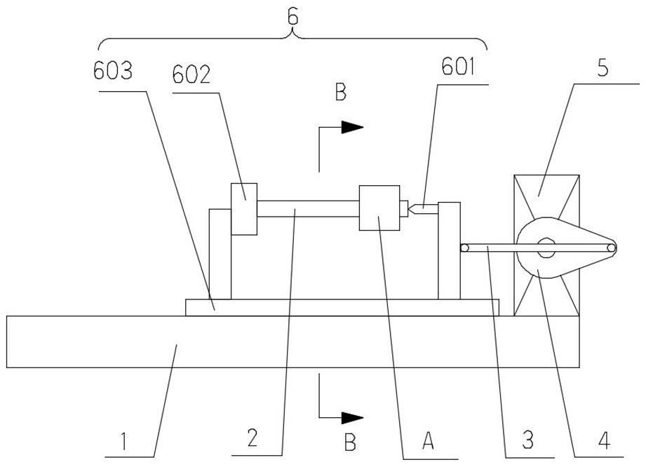
[0045] Such as figure 1 As shown, a longitudinal polishing machine for a rod-shaped sample 2 in this embodiment, the main structure is a horizontal base 1 and a clamping device 6 and a polishing device A arranged on the horizontal base 1 .

[0046] The horizontal base 1 is fixed on a firm ground or a workbench, and its upper edge is a flat horizontal plane.

[0047] The clamping device 6 is used to clamp and fix the sample 2, and can carry the sample 2 along the figure 1 The horizontal left and right linear directions in the middle slide reciprocally on the horizontal base 1. The clamping device 6 includes a slide plate 603 slidably set on the horizontal base 1 , a chuck 602 set at one end of the slide plate 603 , and a tip 601 set at the other end of the slide plate 603 . The sliding plate 603 slides and fits with the upper edge of the horizontal base 1 through two wire rails. A clamping position for fixing the sample 2 is formed between the chuck 602 and the tip 601 , and...

Embodiment 2

[0057] Such as Figure 7 As shown, the main structure of this embodiment is the same as that of Embodiment 1, and both include a horizontal base 1 and a clamping device 6 and a polishing device A arranged on the horizontal base 1. The structures of the horizontal base 1, the clamping device 6 and the device are also approximate. The main difference between this embodiment and embodiment 1 is that the second servo motor 5 is omitted in the present embodiment, and the pressing and relaxing process of the pressing wheel 8 and the update of the polishing abrasive belt 17 are not only driven by the first servo motor 14, And the reciprocating sliding of the clamping device 6 is driven by the first servo motor 14, which further reduces the production cost, and saves the difficulty of cooperation between the first servo motor 14 and the second servo motor 5 and the first servo motor 14 and the second servo motor 5 in Embodiment 1. The deviation generated during the matching process o...

Embodiment 3

[0066] Such as Figure 11 As shown, the structure of Embodiment 2 of this embodiment is basically the same, and only one first servo motor 14 not only drives the pressing and relaxing process of the pressing wheel 8 and the update of the polishing abrasive belt 17, but also drives the clamping process by the first servo motor 14. The reciprocating sliding of the holding device 6. The difference between this embodiment and Embodiment 2 is that the first servo motor 14 drives the clamping device 6 to reciprocate in different ways:

[0067] Such as Figure 12 As shown, the output shaft of the first servo motor 14 is provided with a sixth gear 35 for driving the clamping device 6 to reciprocate and slide, and the sixth gear 35 is a sector gear. One side of the slide plate 603 is provided with a third rack 34 that can be meshed with the sixth gear 35, and one end of the slide plate 603 is also provided with a spring for the slide plate 603 to rebound after the third rack 34 break...


PUM


Abstract

The invention relates to the field of sample processing equipment, in particular to a longitudinal polishing machine for bar-shaped samples. It includes a horizontal base and a clamping device and a polishing device arranged on the horizontal base; the polishing device includes a polishing abrasive belt, a roller for winding and storing the polishing abrasive belt, and an abrasive belt renewal for pulling the polishing abrasive belt out of the roller Mechanism, roller and abrasive belt updating mechanism are respectively located on both sides of the sample axis. The polishing abrasive belt between the roller and the abrasive belt updating mechanism is wound on the sample to form a polishing part, and the polishing sand at both ends of the corresponding polishing part The position of the belt is equipped with pressing wheels, so that the polishing part of the polishing abrasive belt can be closely attached to the circumferential surface of the sample through the two pressing wheels, and then through the reciprocating sliding of the sample with the clamping device and the friction of the polishing abrasive belt The polishing part cooperates with the longitudinal polishing of the sample. Compared with the traditional polishing method, the polishing efficiency, safety and quality of the present invention are greatly improved.

Description

technical field [0001] The invention relates to the field of sample processing equipment, in particular to a longitudinal polishing machine for bar-shaped samples. Background technique [0002] Rod specimens are widely used in the drawing experiments of metal materials to characterize the mechanical properties of metal materials such as strength, hardness, rigidity, plasticity and toughness. The labeled bar-type samples used in the experiment need to be machined to make the bar first, and then the circumferential surface of the bar is polished to reduce its surface roughness, not only to obtain a bright, flat and smooth surface, but also to improve the appearance of the standard sample. aesthetics, and can improve the mechanical properties of the standard specimen itself. [0003] Since the surface to be polished on the bar is a circumferential surface, it cannot be polished by metallographic plane polishing equipment in the prior art. In the prior art, after the drying be...

Claims


Application Information

Patent Timeline
Patent Type & Authority Patents(China)
IPC IPC(8): B24B21/02B24B21/18B24B21/20B24B47/16B24B41/06B24B21/00
CPCB24B21/004B24B21/02B24B21/18B24B21/20B24B41/06B24B47/16
Inventor 张剑睿王刚
Owner 华材科技试验场(洛阳)有限公司
Why Eureka
Try Eureka