Concrete laying and vibrating integrated device used for road construction

A technology for road construction and concrete, which is applied in the field of concrete laying and vibrating integrated device for road construction, which can solve the problems of long construction time and lack of laying function, and achieve the effect of preventing condensation

Inactive Publication Date: 2019-08-09
赣州市兴顺辉科技有限公司
View PDF5 Cites 27 Cited by
  • Summary
  • Abstract
  • Description
  • Claims
  • Application Information

AI Technical Summary

Problems solved by technology

[0004] However, the existing vibrator does not have the function of laying. It needs to use t...

Method used


Image

  • Concrete laying and vibrating integrated device used for road construction
  • Concrete laying and vibrating integrated device used for road construction
  • Concrete laying and vibrating integrated device used for road construction

Examples


Embodiment 1

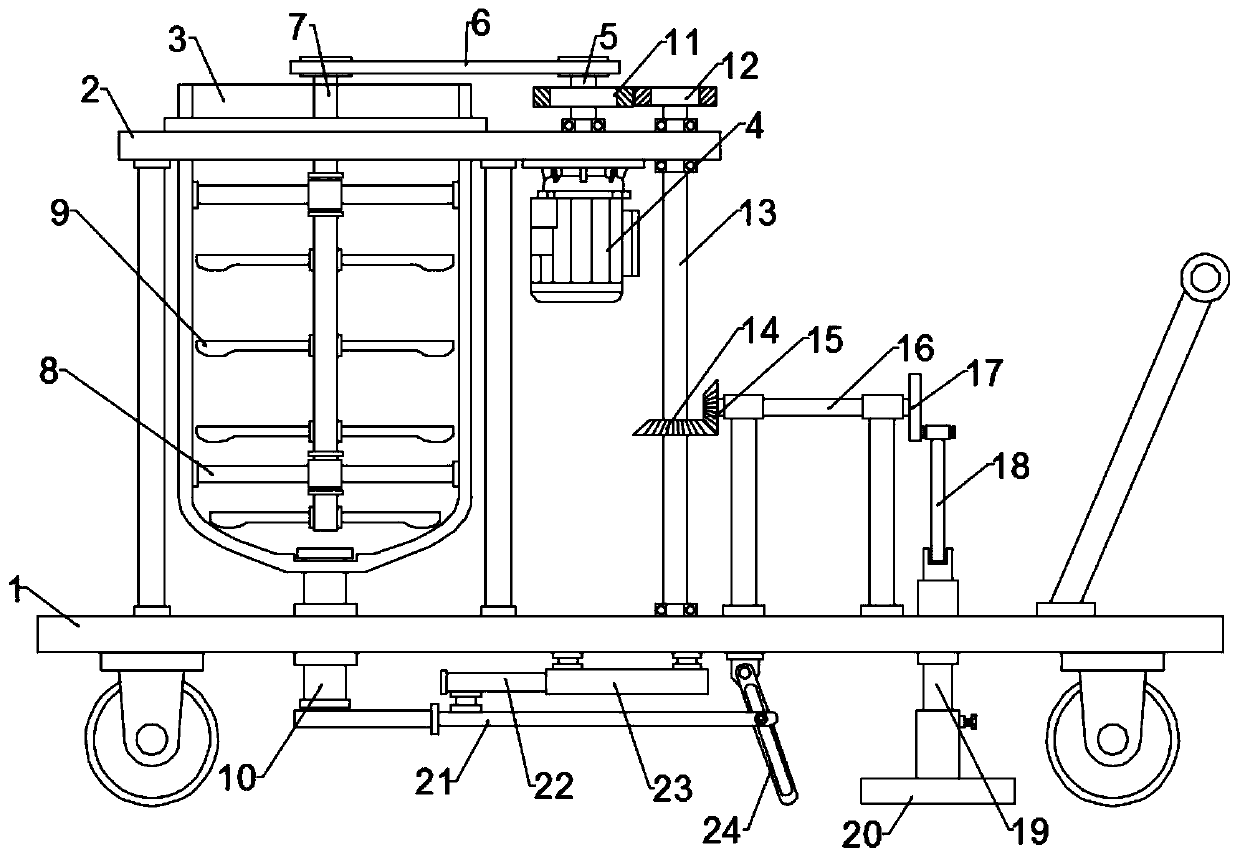
[0022] see Figure 1~3 , in an embodiment of the present invention, a concrete laying and vibrating integrated device for road construction, comprising a bottom plate 1, a top plate 2 fixed on the upper part of the front of the bottom plate 1 through a bracket, and used for feeding the material in the bucket 3 installed on the top plate 2 Mixing components for mixing and vibrating components for compacting the laid concrete beach;

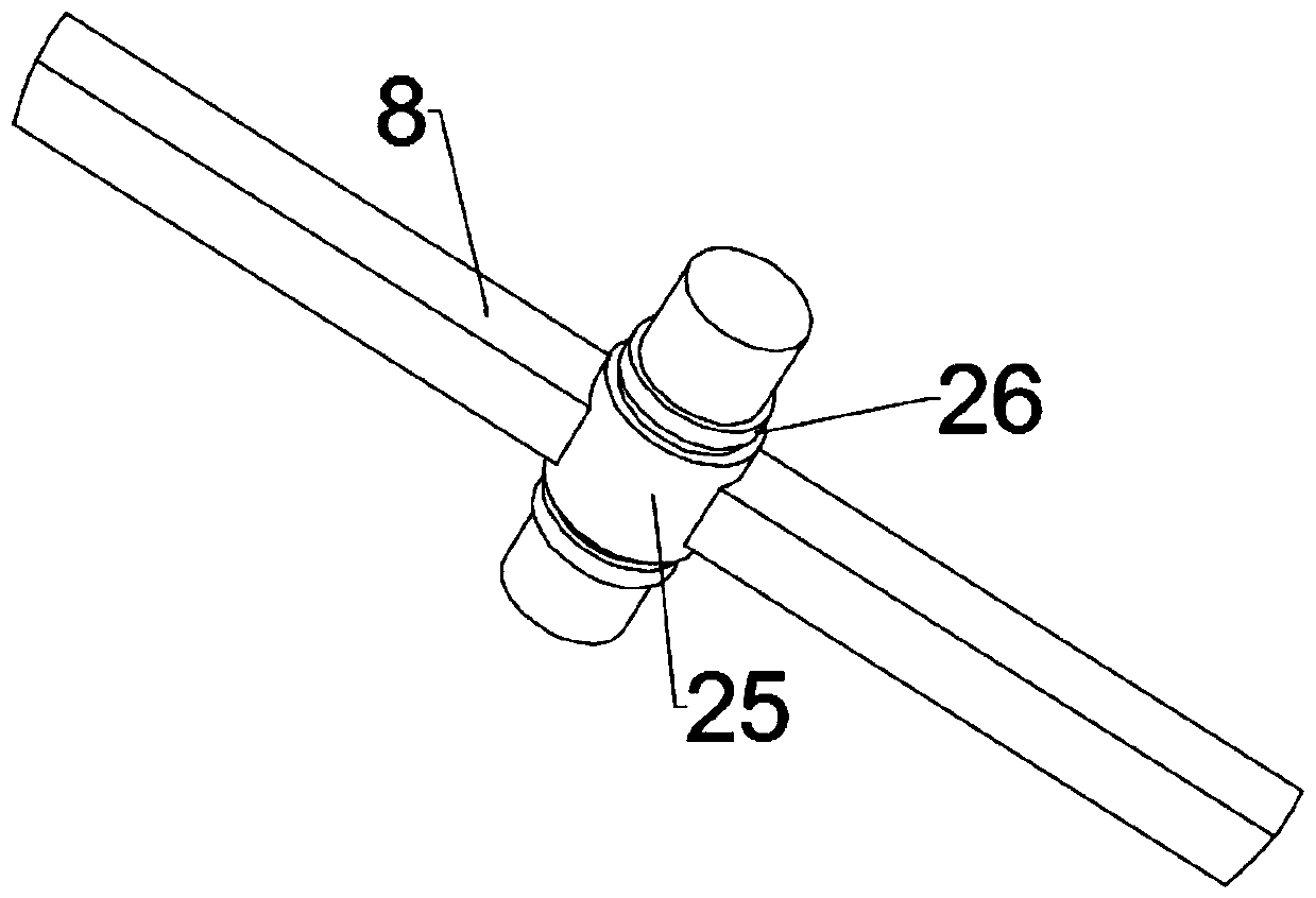
[0023] Specifically, the bottom of the bucket 3 is connected with a discharge pipe 10 for discharging concrete. The discharge pipe 10 passes through the bottom plate 1 and is fixedly connected with it. The flange on one side of the top plate 2 is equipped with a drive motor 4. The output end is connected to the output shaft 5, the output shaft 5 passes through the top plate 2 and is connected with the bearing, and the driving motor 4 is energized to drive the output shaft 5 to rotate; the stirring assembly includes a stirring shaft 7 connected to t...

Embodiment 2

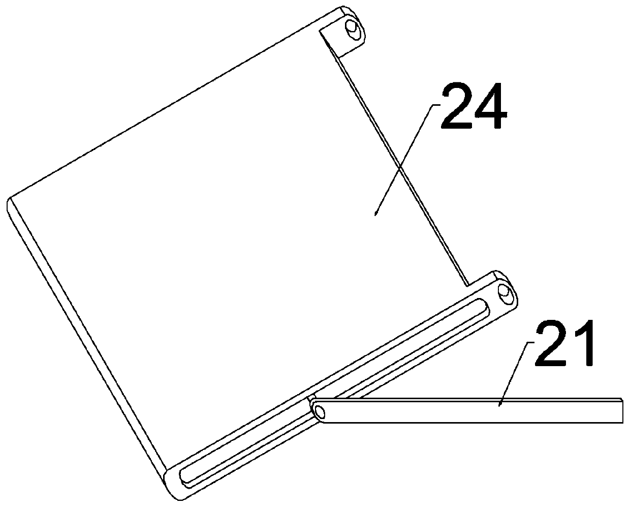
[0027] In order to control the discharge of concrete, the present application provides yet another embodiment. In this embodiment, a concrete laying and vibrating integrated device for road construction also includes a displacement adjustment mechanism. Specifically, the displacement adjustment mechanism includes The adjusting plate 21 which is arranged at the lower opening of the discharge pipe 10 and fits it and the pneumatic assembly fixedly connected to the adjusting plate 21, the pneumatic assembly is composed of a cylinder 23 installed under the bottom plate 1 and a piston rod 22 slidingly connected to the cylinder 23 , the adjustment plate 21 is fixed at the end of the piston rod 22, and the piston rod 22 is driven to slide by the cylinder 23 so as to drive the adjustment plate 21 to move, and the opening size of the lower opening of the discharge pipe 10 is controlled, and finally the concrete displacement is realized. control.

[0028] In order to flatten the discharg...


PUM


Abstract

The invention discloses a concrete laying and vibrating integrated device used for road construction, in particular to a device for stirring a concrete raw material in a material barrel through work of a stirring assembly, driving a driven shaft to rotate through a rotating output shaft, driving a crank-sliding block assembly by the driven shaft through a bevel gear set to work and finally drivinga vibrating board to move up and down in a reciprocating mode to vibrate a pavement. The concrete laying and vibrating integrated device effectively solves the problem that existing pavement concretelaying and vibration are finished through two working procedures, and construction consumes long time. The bottom of the material barrel communicates with a discharging pipe used for discharging concrete, a drive motor is installed on one side of a top board through a flange, and the output end of the drive motor is connected with the output shaft; the stirring assembly comprises a stirring shaftconnected with the upper end of the output shaft through a transmission piece and a stabilization frame, the stirring shaft is sleeved with the stabilization frame, the stabilization frame is installed on the inner wall of the material barrel, and multiple stirring blades are circumferentially fixed to the stirring shaft; and a vibrating assembly is arranged on the rear portion of a bottom boardand connected with the output shaft.

Description

technical field [0001] The invention relates to construction equipment, in particular to a concrete paving and vibrating integrated device for road construction. Background technique [0002] Vibration refers to the process of vibrating and compacting the concrete mixture unloaded into the pouring bin to improve its strength and ensure the quality of concrete components. [0003] When the concrete is poured with a concrete mixer, the air bubbles must be removed and tamped to make the concrete compact and eliminate the honeycomb surface of the concrete, so as to improve its strength and ensure the quality of the concrete components. A concrete vibrator is a machine for mechanically compacting concrete. [0004] However, the existing vibrator does not have the function of laying. It needs to use the pump body to discharge the concrete to the road surface, and then vibrate after leveling. long. Contents of the invention [0005] Based on the deficiencies in the prior art m...

Claims


Application Information

Patent Timeline
IPC IPC(8): E01C19/48B28C5/16B28C5/08
CPCB28C5/0831B28C5/16E01C19/4853E01C2301/02
Inventor 陈万青
Owner 赣州市兴顺辉科技有限公司
Why Eureka
Try Eureka