Flip antenna synchronous stretching system and control method

An unfolding system and flip-up technology, which is applied to antennas, folding antennas, antenna parts, etc., can solve the problems that cannot meet the requirements of erecting large-diameter antenna arrays, small antenna arrays, and long detection distances, etc., and achieve simple control technology Mature, highly controllable, highly automated effects

Inactive Publication Date: 2019-08-09
CHINA ELECTRONIC TECH GRP CORP NO 38 RES INST
View PDF12 Cites 2 Cited by
  • Summary
  • Abstract
  • Description
  • Claims
  • Application Information

AI Technical Summary

Problems solved by technology

The advantages of folded antennas are small size, simple operation, and high reliability. However, the antenna array of existing folded antennas is relatively small, which cannot obtain a long detection distance and cannot meet the erection requirements of large-diameter antenna arrays.

Method used


Image

  • Flip antenna synchronous stretching system and control method
  • Flip antenna synchronous stretching system and control method
  • Flip antenna synchronous stretching system and control method

Examples


Embodiment 1

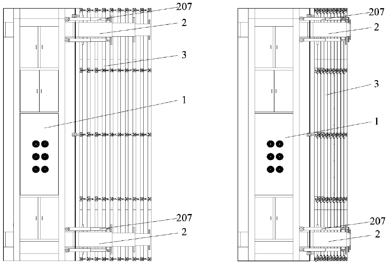
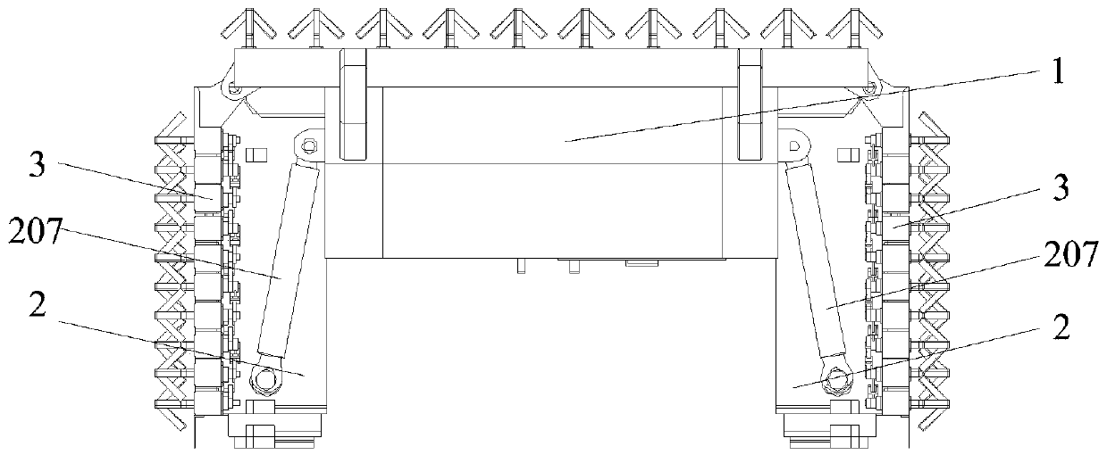
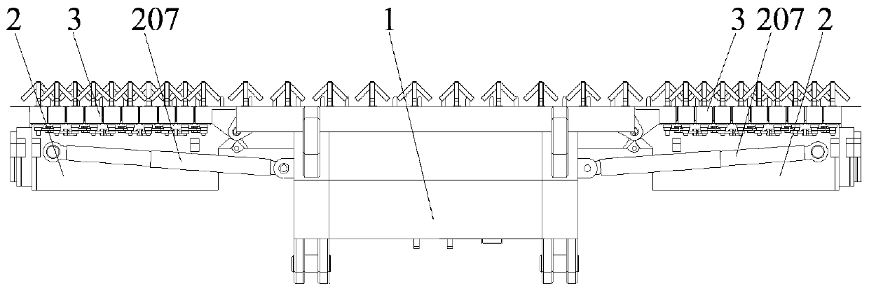
[0027] Such as figure 1 , figure 2 , image 3 as shown, figure 1 It is a bottom view of the structure of the flip-up radar antenna deployment system; figure 2 It is a schematic diagram of the folded state of the flip-up radar antenna deployment system; image 3 It is a schematic diagram of the deployment state of the flip-type radar antenna deployment system; the flip-type radar antenna deployment system of the present invention includes a middle frame 1, a horizontal extension mechanism 2, an antenna column frame 3, and a hydraulic system 4; the middle frame 1 Hinged with the horizontal extension mechanism 2, the horizontal extension mechanism 2 can perform overturning movement around the hinge point, the antenna column skeleton 3 is arranged on the horizontal extension mechanism 2, and the hydraulic system 4 controls the horizontal extension mechanism 2. Realize the turning over and horizontal expansion operation of the horizontal expansion mechanism 2.

[0028] Such ...

Embodiment 2

[0037] Such as Figure 6 as shown, Figure 6 It is the hydraulic structure diagram of the flip radar antenna deployment system; the hydraulic system 4 includes a motor 401, a hydraulic pump 402, a backup hydraulic pump 403, a fuel tank 404, an unloading valve 406, an overflow valve 407, a pressure gauge 408, a high pressure Filter 409, first one-way valve 405, second one-way valve 410, third one-way valve 411, low-pressure filter 412, first electromagnetic proportional reversing valve 413, second electromagnetic proportional reversing valve 414, third Electromagnetic proportional reversing valve 415, fourth electromagnetic proportional reversing valve 416, first group of balance valve 417, second group of balance valve 420, first hydraulic control check valve 418, second hydraulic control check valve 419, third A hydraulically controlled one-way valve 421 , a fourth hydraulically controlled one-way valve 422 , a fifth hydraulically controlled one-way valve 423 , and a sixth h...

Embodiment 3

[0045] The control process of the flip-type antenna synchronous deployment system of the present invention is as follows:

[0046] The controller collects the stroke value data on the pull rod sensor 204 installed on each group of the turning cylinders 207, and sends a control signal according to the stroke difference between the two groups of turning cylinders 207; by controlling the second proportional electromagnetic The energization of the iron D2 and the fourth proportional electromagnet D4 changes the opening degrees of the first electromagnetic proportional reversing valve 413 and the second electromagnetic proportional reversing valve 414 to realize the synchronous control of the turning action.

[0047] The controller collects the stroke value data on the pull rod sensor 204 installed on the two sets of horizontal stretching oil cylinders 208, and sends a control signal according to the stroke difference between the two sets of horizontal stretching oil cylinders 208; ...


PUM


Abstract

The invention discloses a flip antenna synchronous stretching system and a control method. The system includes a central framework, horizontal stretching mechanisms, an antenna column framework and ahydraulic system, wherein the central framework is hinged with the horizontal stretching mechanism, the horizontal stretching mechanisms can perform flipping motion around a hinge point, the antenna column framework is disposed on the horizontal stretching mechanisms, and the hydraulic system controls the horizontal stretching mechanisms for realizing flipping and horizontal stretching operation of the horizontal stretching mechanisms. The system is advantaged in that a side block antenna consists of two sets of horizontal stretching mechanisms, the side block column framework load is evenly distributed on each arm of the two sets of horizontal stretching mechanisms, stiffness of the entire antenna front is improved, and erection requirements of large-diameter antenna fronts are met.

Description

technical field [0001] The invention relates to the technical field of radar antennas, in particular to a flip-up antenna synchronous deployment system and a control method. Background technique [0002] In recent years, the air defense system with ground radar as the core is facing serious threats such as electronic interference, stealth aircraft, and anti-radiation missiles. In order to improve its own survivability, ground radar has the ability to quickly and reliably automatically erect / withdraw the antenna array It is one of its basic requirements. In addition to meeting the rapid maneuvering needs of the battlefield, it also needs to meet the requirements of sea, land and air loading and transportation specifications. [0003] The vehicle-mounted active phased array antenna array is usually folded, turned over and other actions to complete the erection and withdrawal. The advantages of foldable antennas are small size, simple operation, and high reliability. However, ...

Claims


Application Information

Patent Timeline
Patent Type & Authority Applications(China)
IPC IPC(8): H01Q1/08H01Q1/32F15B11/22F15B13/08F15B13/044F15B21/041
CPCF15B11/22F15B13/044F15B13/0807F15B21/041F15B2013/0448H01Q1/08H01Q1/3233
Inventor 赵柱陈建平杜勇孟国军房景仕赵承三
Owner CHINA ELECTRONIC TECH GRP CORP NO 38 RES INST
Why Eureka
Try Eureka