
Wiring body and wiring body assembly

A wiring body and wiring technology, which is applied in the direction of printed circuit components, electrical components, printed circuit components, etc., can solve the problem of damaging the flatness of the wiring body, and achieve the effect of suppressing wetting expansion and excellent flatness

Inactive Publication Date: 2019-08-09
THE FUJIKURA CABLE WORKS LTD
View PDF5 Cites 0 Cited by
  • Summary
  • Abstract
  • Description
  • Claims
  • Application Information

AI Technical Summary

Problems solved by technology

[0005] In the connection structure between the wiring body and the FPC, the wiring body has a first resin part, a conductor part including a terminal part formed on the surface of the first resin part, and a first part covering the part of the conductor part except the terminal part. 2. For the resin part, when the exposed portion of the terminal part of the wiring body is sealed with a sealing resin, there is a problem that the sealing resin wets and expands on the upper surface of the second resin part, thereby impairing the flatness of the entire wiring body.

Method used


Image

  • Wiring body and wiring body assembly
  • Wiring body and wiring body assembly
  • Wiring body and wiring body assembly

Examples


Embodiment Construction

[0038] Embodiments of the present invention will be described below based on the drawings.

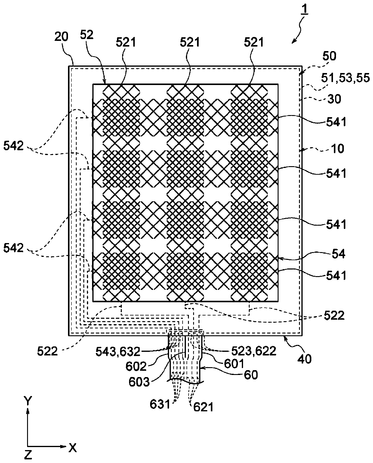
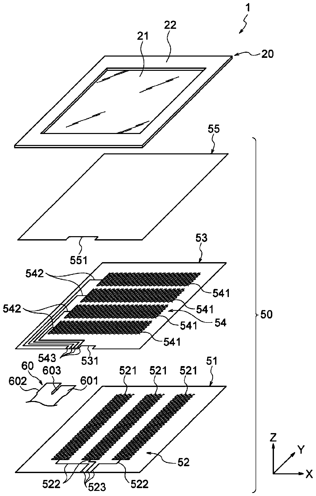
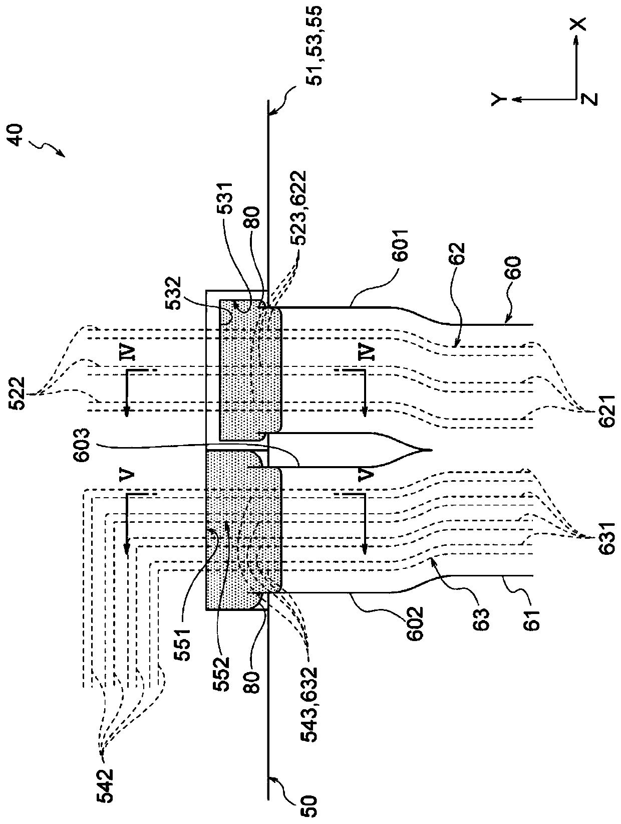
[0039] figure 1 is a plan view showing a touch sensor according to an embodiment of the present invention, figure 2 is an exploded perspective view of its touch sensor, image 3 It is a plan view showing an enlarged connection portion between the first wiring body and the second wiring body.

[0040] figure 1 The illustrated touch sensor 1 is a projected capacitive touch panel sensor, and is used as an input device having a function of detecting a touch position in combination with a display device (not shown), for example. The display device is not particularly limited, and liquid crystal displays, organic EL displays, electronic paper, and the like can be used. This touch sensor 1 has detection electrodes and drive electrodes (first and second electrode portions 521 and 541 described later) arranged to face each other. (not shown) A predetermined voltage is periodically applied...


PUM


Abstract

According to the present invention, a first wiring body 50 is provided with a first resin part 51, a conductor part 52 that is formed on the upper surface of the first resin part and comprises at least a first terminal part 523, and a second resin part 53 that is formed on the upper surface of the first resin part so as to cover the conductor part. The second resin part comprises a first opening 531 from which the first terminal part is exposed; and an end face 532 of the second resin part demarcating the first opening comprises a lower face 533, an upper face 534 that is further from the first resin part than the lower face, and a corner part 535 that connects the lower face and the upper face to each other.

Description

technical field [0001] The present invention relates to a wiring body assembly in which two wiring bodies are connected by a wiring body and a conductive adhesive portion. [0002] For designated countries that recognize citations based on reference documents, the contents described in Japanese Patent Application No. 2017-005654 filed in Japan on January 17, 2017 are incorporated into this specification by reference and become a part of the description of this specification. Background technique [0003] As a connection structure between silver electrode terminals of a color plasma display panel and a flexible printed wiring board (hereinafter referred to as FPC), a structure in which exposed parts of silver electrode terminals are sealed with resin is known (for example, refer to Patent Document 1). [0004] Patent Document 1: Japanese Patent Laid-Open No. 2001-015042 [0005] In the connection structure between the wiring body and the FPC, the wiring body has a first resi...

Claims


Application Information

Patent Timeline
Patent Type & Authority Applications(China)
IPC IPC(8): H05K1/14G09F9/00
CPCH05K3/282H05K1/147H05K1/117H05K1/144H05K2201/041H05K2203/1173H05K2201/09854H05K2201/09154H05K2201/09081H05K2201/052H05K2201/09909H05K1/028H05K2201/10128G06F3/044H05K1/189
Inventor 须藤勇气
Owner THE FUJIKURA CABLE WORKS LTD
Learn More