
Integrated forming method for composite material cabin

A composite material and molding method technology, applied in the field of cabin body molding, can solve the problems that cannot meet the needs of practical applications, increase the overall weight of special vehicles, affect the mobility of special vehicles, etc., to ensure molding stability and molding efficiency, improve Integrity and stability, the effect of stable bonding

Inactive Publication Date: 2019-08-13
HUBEI SANJIANG AEROSPACE WANFENG TECH DEV
View PDF9 Cites 7 Cited by
  • Summary
  • Abstract
  • Description
  • Claims
  • Application Information

AI Technical Summary

Problems solved by technology

[0004] At present, most of the traditional power battery compartments are welded and riveted with the skin and skeleton of aluminum alloy materials. Due to the high metal density, the density of aluminum alloy materials can often reach 2.54g / cm 3 , which greatly increases the overall weight of special vehicles, affects the mobility of special vehicles, and has gradually failed to meet the needs of practical applications
At the same time, during the forming process of the existing power battery compartment, its skin often needs to be assembled on the frame through various mounting parts, which also increases the overall weight of the compartment to a certain extent and affects the mobility of special vehicles

Method used


Image

  • Integrated forming method for composite material cabin
  • Integrated forming method for composite material cabin
  • Integrated forming method for composite material cabin

Examples


Embodiment Construction

[0040] In order to make the object, technical solution and advantages of the present invention clearer, the present invention will be further described in detail below in conjunction with the accompanying drawings and embodiments. It should be understood that the specific embodiments described here are only used to explain the present invention, not to limit the present invention.

[0041] In addition, the technical features involved in the various embodiments of the present invention described below can be combined with each other as long as they do not constitute a conflict with each other.

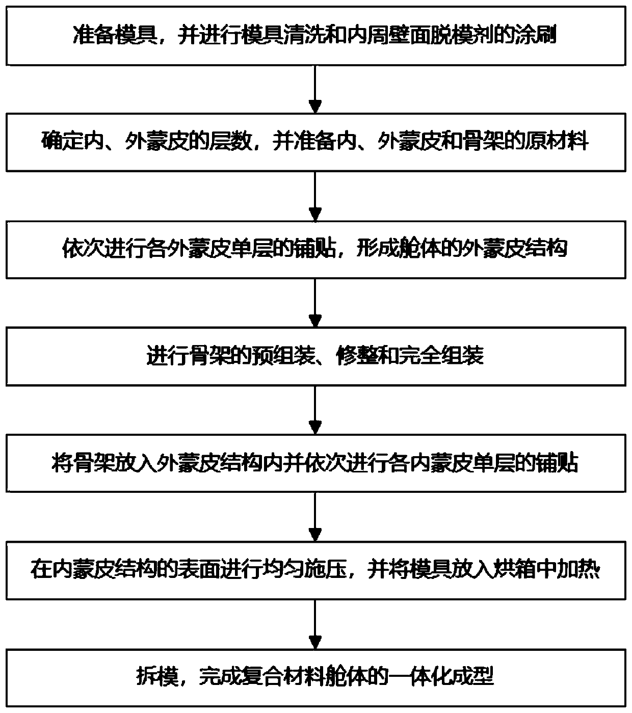
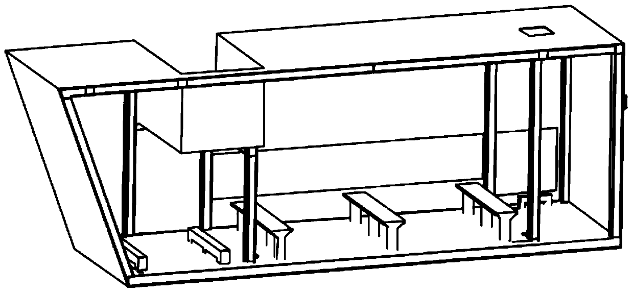
[0042] In the preferred embodiment of the present invention, the steps of the integrated molding method applicable to the composite cabin body are as follows: figure 1As shown in , it can be used as figure 2 The integrated molding of the composite material cabin shown in , the composite material cabin can be used as a power battery pack cabin.

[0043] Specifically, the steps of the ...


PUM

PropertyMeasurementUnit
Thicknessaaaaaaaaaa

Abstract

The invention discloses an integrated forming method for a composite material cabin, and belongs to the technical field of cabin forming. According to the integrated forming method, a die corresponding to the cabin in shape is arranged and internally and sequentially provided with an outer skin structure, a framework and an inner skin structure; through layering paving and pasting of inner and outer skin materials, the framework can be effectively wrapped in the inner skin structure and the outer skin structure, an integrated integral structure is formed, and the weight of the cabin is greatlyreduced under the situation that the structure strength of the cabin is guaranteed. According to the integrated forming method for the composite material cabin, the steps of the integrated forming method are simple, operation is simple and convenient, integrated forming of the composite material cabin can be effectively achieved, and it is ensured that the cabin has good integral performance after being formed; and the weight of the cabin is greatly reduced compared with an existing metal cabin, the maneuverability of a weapon system loading the cabin is effectively improved, and good application prospects and popularization value are achieved.

Description

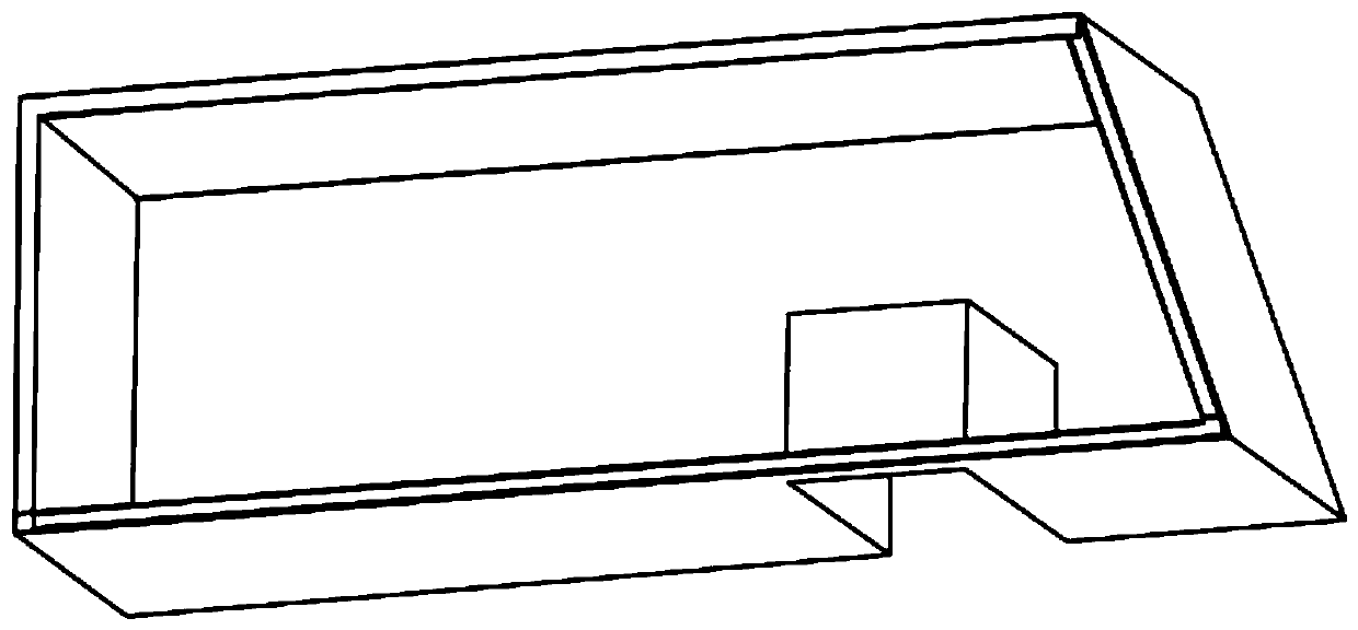
technical field [0001] The invention belongs to the technical field of cabin body forming, and in particular relates to an integrated molding method for a composite material cabin body. Background technique [0002] With the continuous advancement of science and technology and the increasing development of weapon systems, there is a higher demand for the rapid maneuverability of the weapon system, which also puts forward a higher technology for the lightweight of various installation cabins in the weapon system Require. [0003] Among all kinds of installation cabins, the power battery pack cabin is particularly widely used. It is often installed independently on the chassis of special vehicles. It has a large size and most of its shapes are non-standard square cabins. figure 2 shown in . Normally, six sets of batteries and a set of lightning protection devices can be installed inside the power battery pack compartment to provide power for the electrical equipment on the v...

Claims


Application Information

Patent Timeline
IPC IPC(8): B29C70/34B29C70/54
CPCB29C70/34B29C70/54
Inventor 孙雪芳张和平刘敏欧阳洁花彤历奂玖平邓平盛
Owner HUBEI SANJIANG AEROSPACE WANFENG TECH DEV
Learn More