
High permeability heat transfer printing machine

A high-permeability, heat-transfer technology, applied to rotary printing machines, printing machines, transfer printing, etc., can solve the problems of increasing blanket covering surface, insufficient penetration rate, and low product quality, so as to improve the printing and dyeing effect Effects on product quality, ink transfer rate increase, and dye penetration rate improvement

Pending Publication Date: 2019-08-13
江苏康尼纺织品有限公司
View PDF0 Cites 0 Cited by
  • Summary
  • Abstract
  • Description
  • Claims
  • Application Information

AI Technical Summary

Problems solved by technology

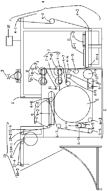
[0004] In order to solve the above problems, the present invention discloses a high-permeability thermal transfer printing machine. The surface layer cannot reach the bottom of the fabric, and the dye penetration is not enough, not to mention printing and dyeing ultra-high weight Raschel cloud blankets, whose long fibers cannot penetrate the roots efficiently with existing ordinary heat transfer printing machines. Poor printing and dyeing results lead to low product quality and waste of resources. After research, the main reason for the inability to reach the penetration rate is that the wrapping angle of the blanket attached to the hot roller is too small, which causes the plush printing carrier to be transferred by heat. The length is not enough. The covering surface of the blanket of ordinary thermal transfer printing machine is about 55%. To improve the printing and dyeing efficiency, it is necessary to increase the covering surface. Under the premise that the transfer paper and plush printing carrier can run normally and smoothly The covering surface should be maximized, that is, the wrapping angle between the hot roller and the blanket of the thermal transfer printing machine should be maximized, and the index should be between 70% and 75% as the standard, leaving 30% to 25% The main measure is to increase the covering surface of the blanket by adjusting the arrangement of the tension rollers inside the thermal transfer printing machine.

Method used


Image

  • High permeability heat transfer printing machine

Examples


Embodiment 1

[0031] Embodiment 1: see figure 1Now, a high-permeability thermal transfer printing machine provided by the present invention will be described. The present invention provides the following technical solutions: a high-permeability thermal transfer printing machine, including a heat roller 5, a frame 1, an operating device 2, a cloth feeding device 7 and a tensioning system 6, wherein the heat roller 5 is set Inside the frame 1, the frame 1 is provided with an operating device 2, the operating device 2 includes an operating platform 2-1 and a carriage 2-2, and the cloth feeding device 4 is arranged on the right side of the carriage 2-2 , the cloth feed device 4 consists of the first cloth feed roller 4-1, the second cloth feed roller 4-3, the third cloth feed roller 4-4, the fourth cloth feed roller 4-6 and the fifth cloth feed roller arranged in sequence Cloth rollers 4-7, the tensioning system 6 is composed of tensioning rollers, the first tensioning roller 6-1, the second t...

Embodiment 2

[0032] Example 2: see figure 1 , as an improvement of the present invention, the high-permeability thermal transfer printing machine also includes a paper feeding device 7 and a paper delivery device 8, and the paper feeding device 7 includes a first paper feeding roller 7-1 and a second paper feeding roller 7-1 Roller 7-2, the paper delivery device 8 includes a first paper delivery roller 8-1 and a second paper delivery roller 8-2. The paper feeding device 7 and the paper receiving device 8 are ingenious in design, simple and clear in structure, and are closely connected with each component without interfering with each other, making it easy to maintain the product during use in the future.

Embodiment 3

[0033] Embodiment 3: see figure 1 , as an improvement of the present invention, the first paper feed roller 7-1 and the second paper feed roller 7-2 are fixed on the frame 1 through the first fixing bracket 7-3, and the first The paper delivery roller 8-1 and the second paper delivery roller 8-2 are fixed on the frame 1 through the second fixed frame 8-3. Fixing the paper feeding device 7 and the paper delivery device 8 on the frame 1 through the fixed frame can significantly improve the working stability of the thermal transfer printing machine. In the actual production process, the transfer paper is very heavy. Then in uninterrupted work, the fixed frame can improve the working stability of the paper feeding device 7 and the paper delivery device 8, ensuring the safety of the working environment of the operator.


PUM


Abstract

The invention discloses a high permeability heat transfer printing machine. The printing machine consists of a hot roller, a frame, an operation device, a cloth feeding device, a tensioning system, apaper collecting device, a paper feeding device, a cropping device, a paper pressing roller, a hoist and a motor. The printing machine is ingenious in design and simple and intelligible in structure,and assemblies can be tightly connected to each other but do not influence on each other, so that the easy maintenance of the product during using in the future can be achieved; and the arrangement modes of tension rollers are adjusted, so that the coating surface between the hot roller and a blanket can be increased from traditional 55% to 70-75%, 30-25% space can be left to perform cloth feedingand discharging and paper collecting, and therefore, the normal flattening operation of transfer paper and plush printing carriers can be guaranteed so that the increasing of the coating surface of the blanket can be achieved, the heat transfer length of the plush printing carriers can be increased, the time of printing ink transferring can be prolonged, the transfer rates of printing ink can begreatly increased, correspondingly, the printing ink permeability of printing can be increased as well, printing and dyeing effects and product quality can be enhanced, reject rates can be reduced, and degree of automation can be enhanced.

Description

technical field [0001] The invention relates to the field of printing and dyeing equipment, in particular to a heat transfer printing machine with high permeability. Background technique [0002] Thermal transfer printing is a new printing and dyeing process that has gradually emerged internationally in recent years. First of all, use advanced printing technology to print special printing and dyeing (water-based or oil-based), and print all required patterns on special paper to make transfer printing paper with various patterns. Then, on the transfer printing machine, transfer After the patterned side of the decal paper is closely bonded to the printed fabric, through the action of heat and pressure, the dyes of the decal paper are sublimated and transferred to the printed fabric to form various patterns on the printed fabric. pattern. [0003] At present, the printing and dyeing of high-weight plush cloth in the world still uses traditional magnetic bar dispersion printin...

Claims


Application Information

Patent Timeline
IPC IPC(8): B41F16/02
CPCB41F16/02
Inventor 刘林玉
Owner 江苏康尼纺织品有限公司
Learn More