
Screenless secondary printing method for positive electrode of crystalline silicon solar cell

A solar cell and secondary printing technology, which is applied to circuits, photovoltaic power generation, electrical components, etc., can solve problems such as insufficient operator skills, increased component welding debris, and reduced shading area, achieving excellent line shape and aspect ratio, Reduced series resistance and improved collection area

Inactive Publication Date: 2019-03-05
TONGWEI SOLAR ENERGY (CHENGDU) CO LID
View PDF4 Cites 1 Cited by
  • Summary
  • Abstract
  • Description
  • Claims
  • Application Information

AI Technical Summary

Problems solved by technology

However, in the traditional screen printing process, one kind of paste is used to print the main grid lines and sub grid lines at the same time. The increase of the height of the busbar not only does not significantly help the electrical performance, but will increase the unit consumption of the paste and increase the cost. At the same time, the height of the busbar is too high, which will also increase the welding debris of the module, which will easily lead to the scrapping of the solar cell.
[0005] Therefore, in theory, the printing of the positive electrode of the solar cell is divided into two printings, which can achieve a significant increase in height compared to a single printing on the basis of thinning the width of the printed grid lines, thereby reducing the shading area. , on the basis of improving the short-circuit current, it ensures that the fill factor is not lost. Therefore, the use of secondary printing technology has become an effective method to improve conversion efficiency today. Insufficient and other factors, the effect of grid line printing is not ideal
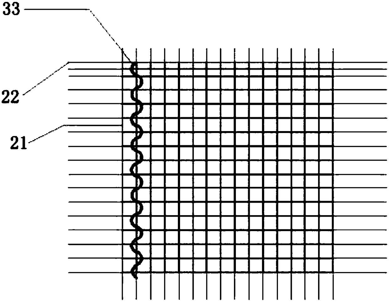
[0006] In addition, most of the currently used screen printing screens are 22.5° oblique screens. The network knots formed by the latitude and longitude lines on the screen will affect the passage of printing paste, resulting in poor printing line uniformity, easy to block the screen, and lines. Problems such as virtual prints and broken grids caused by missing graphics, and the width of the grid lines cannot be made too narrow, resulting in a significant decline in the grade and electrical performance of the cell

Method used


Image

  • Screenless secondary printing method for positive electrode of crystalline silicon solar cell
  • Screenless secondary printing method for positive electrode of crystalline silicon solar cell
  • Screenless secondary printing method for positive electrode of crystalline silicon solar cell

Examples


Embodiment Construction

[0034] In order to enable those skilled in the art to better understand the technical solutions of the present invention, the present invention will be further described in detail below in conjunction with the accompanying drawings and preferred embodiments. It should be noted that the following preferred embodiments should not be regarded as limiting the present invention, and the protection scope of the present invention should be determined by the scope defined in the claims. For those skilled in the art, without departing from the spirit and scope of the present invention, some improvements and modifications can also be made, and these improvements and modifications should also be regarded as the protection scope of the present invention.

[0035]The invention provides a non-network secondary printing method for the positive electrode of a crystalline silicon solar cell, which includes two printings of DP1 and DP2 by using a screen printing machine. The grid lines and auxi...


PUM


Abstract

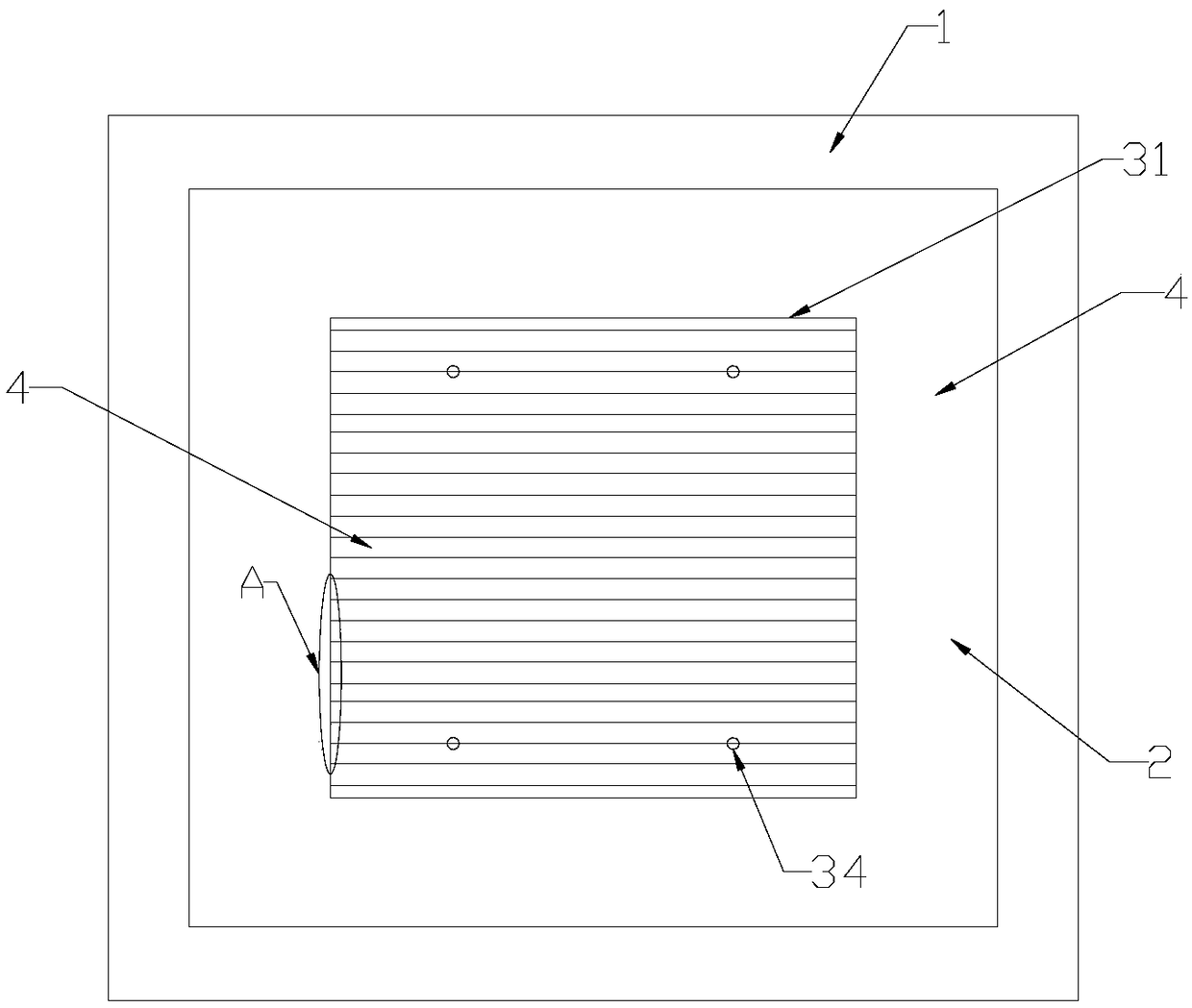
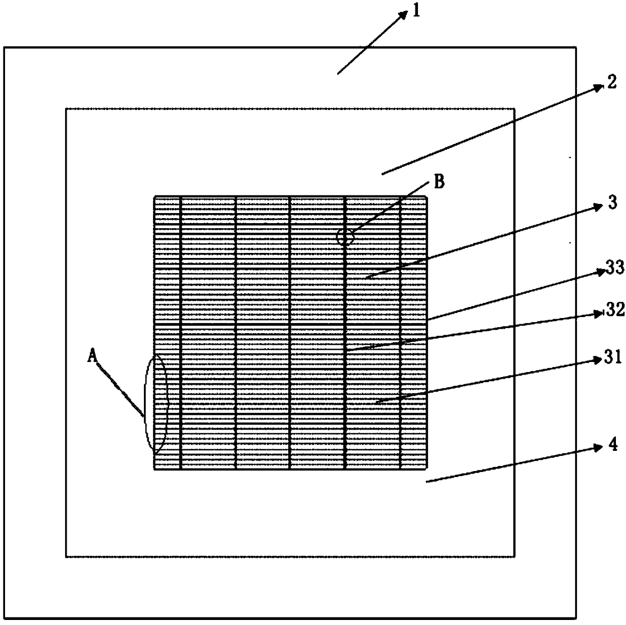
The present invention discloses a screenless secondary printing method for a positive electrode of a crystalline silicon solar cell. The method comprises that: a silk-screen printing machine is used to perform two times of printing of DP1 and DP2, wherein the sub-grid line is printed in the DP1, the main grid line and the sub-gate are printed in the DP2, and the silk-screen printing plate used forDP1 and DP2 printing is a screenless silk-screen printing late; the sub-grid line and the positioning points are printed onto the cell sheet by using the slurry through the DP1 screenless silk-screenprinting plate; four solid positioning points on the cell sheet is captured by using the HD camera, and the cell sheet is automatically adjusted to the appropriate position to achieve precise contrast with the alignment point on the DP2 screenless silk-screen printing plate; and the main grid line and the sub-grid line are printed onto the cell sheet by using the slurry through the DP2 screenlesssilk-screen printing plate. According to the method disclosed by the present invention, the limitations of the traditional printing process is broken through, the aspect ratio of the sub-grid printing is improved, the printing quality of the grid line is improved, and the electrical performance and the excellent product rate of the cell sheet are improved.

Description

technical field [0001] The invention belongs to the technical field of solar cell preparation, and in particular relates to a non-network secondary printing method for a positive electrode of a crystalline silicon solar cell. Background technique [0002] With the increasing tension of global energy sources, solar energy has been widely valued by countries all over the world due to its unique advantages such as no pollution and large market space. Solar cell, also known as "solar chip" or "photovoltaic cell", is a device that uses the photovoltaic effect to directly convert solar energy into electrical energy. It mainly includes crystalline silicon cells, semiconductor cells, inorganic cells, organic cells, etc., among which crystalline silicon solar cells Dominant position in the mainstream of the market. The structure of crystalline silicon solar cells mainly includes front suede, front p-n junction, front anti-reflection film, front and back electrodes and other parts. A...

Claims


Application Information

Patent Timeline
Patent Type & Authority Applications(China)
IPC IPC(8): H01L31/0224
CPCH01L31/022425Y02E10/50
Inventor 吴俊旻扈静杨蕾
Owner TONGWEI SOLAR ENERGY (CHENGDU) CO LID
Learn More