Supercharge Your Innovation With Domain-Expert AI Agents!

Light-emitting element drive circuit

A technology of light-emitting components and drive circuits, which is applied in the direction of circuits, electrical components, laser components, etc., and can solve problems such as inability to reach quickly and low current level

Active Publication Date: 2020-09-01
RICHTEK TECH
View PDF6 Cites 0 Cited by
  • Summary
  • Abstract
  • Description
  • Claims
  • Application Information

AI Technical Summary

Problems solved by technology

During the time T1, the load current iLOAD can only draw current from the capacitor C2, however, such a current level is still very low (eg figure 2 The waveform diagram of the load current Iload within the time T1 shown)
[0004] In addition, in the prior art, the load current iLOAD is related to the level of the feedback signal FB. Therefore, another major disadvantage of the prior art is: when the feedback signal FB drops below the reference voltage VREF (such as but not limited to 0.2V ) level is still low, due to excessive overshoot (overshoot) effect, the feedback signal FB may be as low as but not limited to 0.1V, because the load current iLOAD is related to the level of the feedback signal FB, therefore, too low feedback The signal FB level will also cause the load current iLOAD to fail to quickly reach its target current level Ip, where the target current level Ip is, for example, the load current level corresponding to the feedback signal FB being 0.2V

Method used


Image

  • Light-emitting element drive circuit
  • Light-emitting element drive circuit
  • Light-emitting element drive circuit

Examples


Embodiment Construction

[0067] The drawings in the present invention are all schematic diagrams, mainly intended to show the coupling relationship between various circuits and the relationship between various signal waveforms. As for the circuits, signal waveforms and frequencies, they are not drawn to scale.

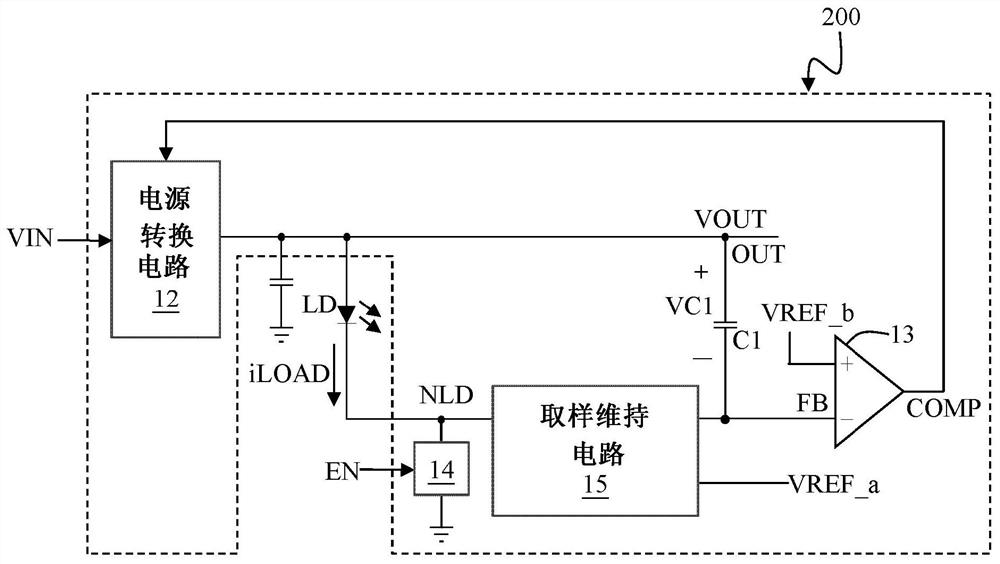
[0068] Please refer to image 3 and Figure 4 . image 3 A schematic block diagram of an embodiment of the light-emitting device driving circuit of the present invention is marked. Figure 4 An embodiment of the load current generating circuit of the present invention is indicated.

[0069] Such as image 3 As shown, the light-emitting element driving circuit 200 of the present invention is used to provide a load current iLOAD to a light-emitting element LD to drive the light-emitting element LD to emit light, wherein the light-emitting element LD can be, for example but not limited to, a laser light-emitting diode. Such high-energy light-emitting elements require extremely high driving cu...


PUM


Abstract

A light-emitting element driving circuit, comprising: a power conversion circuit, an error amplification circuit, a sampling and holding circuit, a load current generating circuit and a feed-forward capacitor. During the non-enabled phase, the feedback signal is electrically connected to the second reference voltage through the sample-and-hold circuit and is disconnected from the load node, thereby, at the transition time point from the non-enabled phase to the enabled phase, the feed-forward The capacitor samples a sampled voltage. In the enable phase, the feedback signal is disconnected from the second reference voltage through the sample-and-hold circuit and coupled to the load node, and the sample voltage is maintained through the feed-forward capacitor, so that within the preset current rise time after the turning point , the difference between the feedback signal and the first reference voltage is large enough, so that the load current rises to reach the first current level within a predetermined current rising time.

Description

technical field [0001] The present invention relates to a light-emitting element driving circuit, in particular to a method of improving the load-transient response of the light-emitting element driving circuit through a sample-and-hold circuit, so that the load current can rise rapidly within a preset current rising time , to drive the light-emitting element to achieve the target current level. Background technique [0002] Please refer to figure 1 and figure 2 . figure 1 Mark the schematic diagram of the light-emitting element driving circuit in the prior art. figure 2 A schematic diagram of the waveform of the operating signal of the light-emitting element driving circuit in the prior art is marked. [0003] In the light-emitting element driving circuit 100 of the prior art, when the light-emitting element driving circuit 100 is in the non-enabled phase (that is, when the enable signal EN is at a low level), the level of the load current iLOAD is zero, and at this t...

Claims


Application Information

Patent Timeline
Patent Type & Authority Patents(China)
IPC IPC(8): H01S5/042
CPCH01S5/042G11C27/02H05B45/37H05B45/395H05B47/10
Inventor 杨奂箴黄宗伟郑惠文林水木
Owner RICHTEK TECH
Features
  • R&D
  • Intellectual Property
  • Life Sciences
  • Materials
  • Tech Scout
  • Unparalleled Data Quality
  • Higher Quality Content
  • 60% Fewer Hallucinations
Learn More