
A micro-nano injection molding mold cavity heating system and heating method thereof

An injection molding and heating system technology, applied in the field of polymer molding, can solve the problems of large heat loss and inaccurate cavity temperature control, and achieve the effect of increasing shear friction, improving friction heat generation efficiency, and avoiding temperature rise

Inactive Publication Date: 2021-04-06
SOUTHWEAT UNIV OF SCI & TECH
View PDF7 Cites 0 Cited by
  • Summary
  • Abstract
  • Description
  • Claims
  • Application Information

AI Technical Summary

Problems solved by technology

[0003] The present invention aims to solve the technical problems that the existing micro-nano injection molding mold heating technology adopts the way of overall heating of the mold, the heat loss is large, and there is inaccurate cavity temperature control, and provides a micro-nano injection molding mold cavity heating system and its heating method

Method used


Image

  • A micro-nano injection molding mold cavity heating system and heating method thereof

Examples


specific Embodiment approach 1

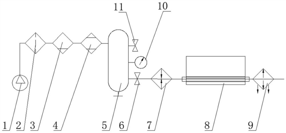
[0027] Embodiment 1: In this embodiment, a micro-nano injection molding mold cavity heating system includes an air compressor 1, a filter 2, a water separator 3, an air dryer 4, an air storage tank 5, a ball valve 6, and a heater. 7. Mould inserts with holes 8, cooler 9; wherein, the air compressor 1 is communicated with the air inlet of the filter 2, the air outlet of the filter 2 is communicated with the air inlet of the water separator 3, and the air outlet of the water separator 3 It is communicated with the air inlet of the air dryer 4, the air outlet of the air dryer 4 is communicated with the air inlet of the air storage tank 5, the air outlet of the air storage tank 5 is communicated with the air inlet of the heater 7, and the connection between the air storage tank 5 and the heater 7 is connected. A ball valve 6 is provided between, the air outlet of the heater 7 is communicated with the air inlet of the die insert 8 with holes, and the air outlet of the die insert 8 w...

specific Embodiment approach 2

[0029] Embodiment 2: The difference between this embodiment and Embodiment 1 is that when a plurality of through holes are opened in the die insert 8 with holes, the plurality of through holes are arranged in a single row, parallel to the bottom edge of the die insert, and the hole spacing is 3~5mm. Others are the same as the first embodiment.

[0030] In this embodiment, multiple through holes are arranged to further realize uniform heating of the mold cavity and improve the heating effect.

specific Embodiment approach 3

[0031] Embodiment 3: The difference between this embodiment and Embodiment 1 or 2 is that the distance between the through hole and the bottom of the mold cavity is 6-10 mm. Others are the same as in the first or second embodiment.

[0032] In this embodiment, the distance between the through hole and the bottom of the mold cavity is limited to 6-10 mm, so as to ensure that the rigidity and strength of the mold insert meet the molding requirements when the melt is filled.


PUM

PropertyMeasurementUnit
strengthaaaaaaaaaa

Abstract

A micro-nano injection molding mold cavity heating system and a heating method thereof, the invention relates to the technical field of polymer molding. The invention aims to solve the technical problems that the existing micro-nano injection mold heating technology adopts the mode of overall heating of the mold, the heat loss is large, and the temperature control of the mold cavity is inaccurate. The system includes air compressor, filter, water separator, air dryer, air receiver, ball valve, heater, perforated mold insert, cooler; heater air outlet and perforated mold insert inlet The mouth is connected, and the air outlet of the mold insert with holes is connected with the air inlet of the cooler. Method: Preheat the mold insert with heated gas, and then let the high-pressure air flow pass through the hole at the bottom of the mold cavity insert to heat the mold cavity. The invention controls the mold cavity temperature to be constant by adjusting the gas pressure. Using high-speed airflow to generate shear friction heat and locally heat the mold, so as to achieve the purpose of energy saving. The invention is used for heating mold cavity.

Description

technical field [0001] The present invention relates to the technical field of polymer molding. Background technique [0002] With the rapid development of micro-nano technology, micro-nano injection molding is one of the most promising polymer micro / nano device fabrication technologies. During micro-nano injection molding of polymer melt, the heat of the melt is easily dissipated due to the large cavity-to-body ratio. In order to ensure the quality of the mold filling, it is usually necessary to heat the mold to a certain temperature. This temperature is higher than that of traditional injection molds. The micro-nano cavity is usually installed on the mold base as an insert, which is characterized by a small size and a small heating area. However, the current micro-nano injection mold heating technology adopts the overall heating method of the mold, which has a large heat loss and the technical problem of inaccurate control of the cavity temperature. SUMMARY OF THE INVE...

Claims


Application Information

Patent Timeline
Patent Type & Authority Patents(China)
IPC IPC(8): B29C45/73B29C45/78
CPCB29C45/7337B29C45/78B29C2945/76531
Inventor 徐斌李光明薛松
Owner SOUTHWEAT UNIV OF SCI & TECH
Learn More