Method and device for vehicle cabin heating

A technology for carriages and electric heaters, applied in measuring devices, exhaust devices, noise reduction devices, etc., can solve problems such as engine power parasitic loss

Pending Publication Date: 2019-08-16
FORD GLOBAL TECH LLC
View PDF0 Cites 3 Cited by
  • Summary
  • Abstract
  • Description
  • Claims
  • Application Information

AI Technical Summary

Problems solved by technology

However, operating the electric heater via the on-boa

Method used


Image

  • Method and device for vehicle cabin heating
  • Method and device for vehicle cabin heating
  • Method and device for vehicle cabin heating

Examples


Embodiment Construction

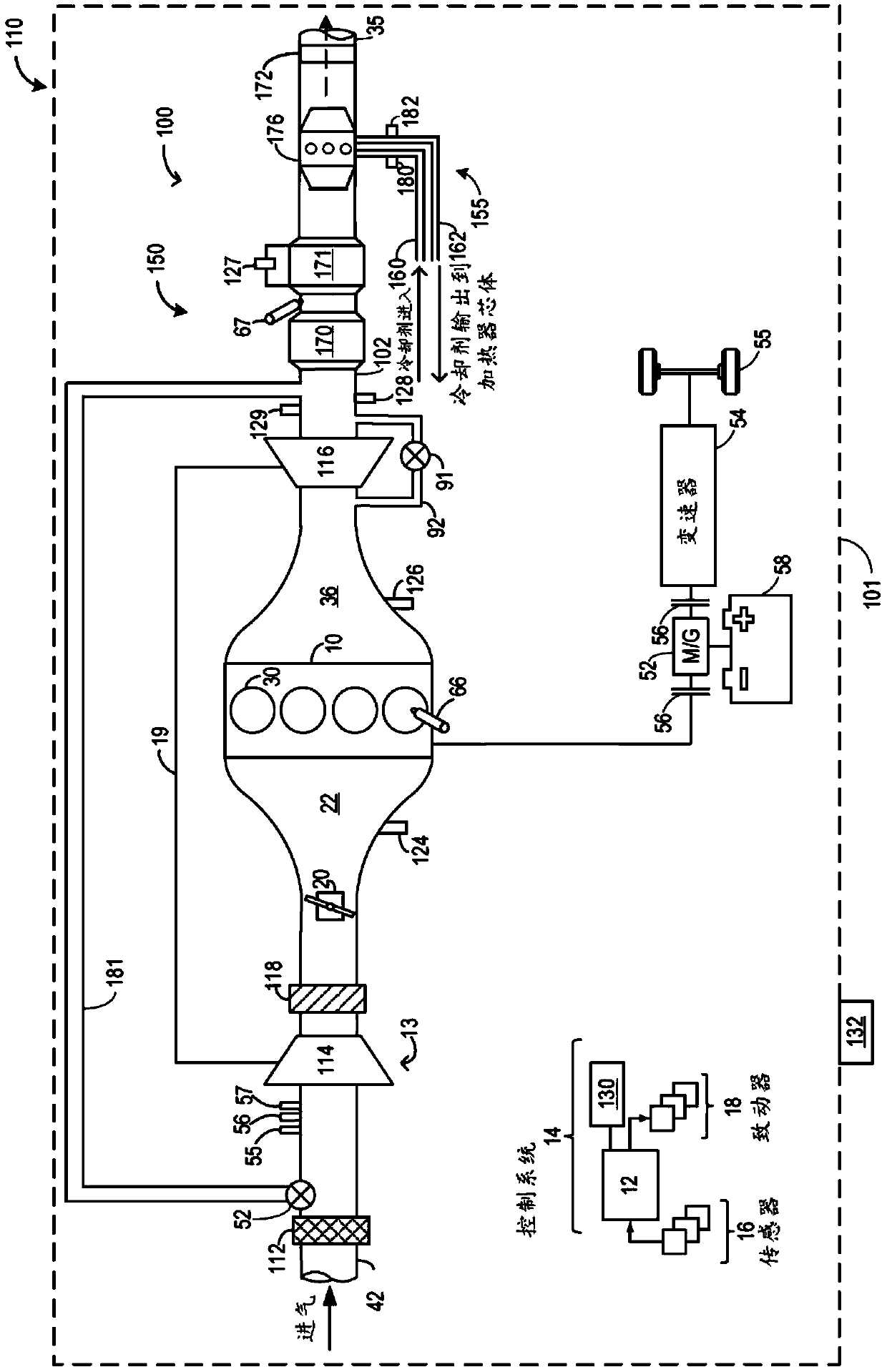
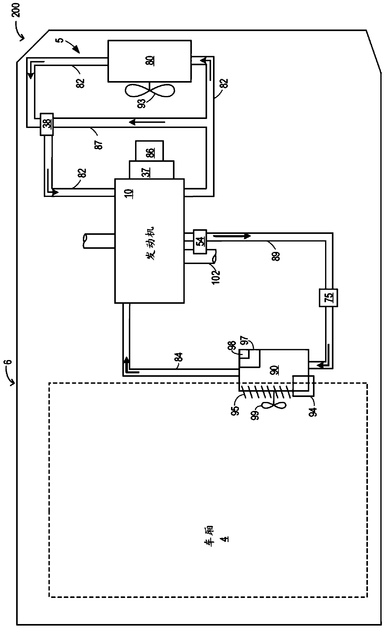
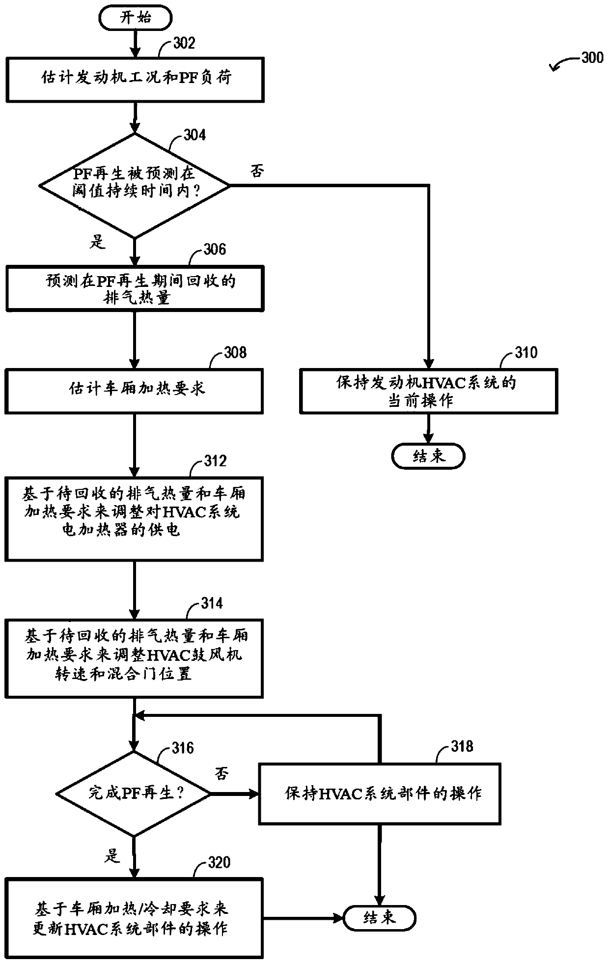
[0013] The following description relates to systems and methods for adjusting one or more components of an onboard vehicle heating, ventilation and air conditioning (HVAC) system based on predicted particulate filter (PF) regeneration events. exist figure 1 An exemplary engine system including an exhaust heat exchanger and a particulate filter is shown in . Such as figure 2 As shown in , the exhaust heat exchanger is coupled to the HVAC system. The engine controller can be configured to execute control programs such as image 3 An exemplary procedure to utilize exhaust heat available during a PF regeneration event and adjust HVAC system components prior to initiating the PF regeneration event. exist Figure 4 Exemplary adjustments to the HVAC system in anticipation of an upcoming PF regeneration event are shown in .

[0014] figure 1 A schematic diagram 110 of a vehicle system 101 having an exemplary engine system 100 including an engine 10 is shown. In one example, en...


PUM


Abstract

Methods and systems are provided for adjusting a vehicle cabin heating system, based on particulate filter (PF) regeneration prediction. In one example, a method includes predicting an amount of exhaust heat that may be recovered via an exhaust heat exchanger during an upcoming PF regeneration event, and prior to the PF regeneration event, adjusting an amount of electric power supplied to an electric heater of the cabin heating system. The amount of adjustment may be based on the predicted amount of exhaust heat that may be recovered.

Description

technical field [0001] The present description generally relates to methods and systems for adjusting a heating ventilation and air conditioning (HVAC) system based on particulate filter regeneration predictions. Background technique [0002] The waste heat generated during combustion can be effectively used to provide heat to the vehicle cabin. Engine coolant circulating through the engine and through the exhaust heat exchanger can extract heat energy from the engine and exhaust, which can be transferred to the heater core of the vehicle's HVAC system. The extracted energy can be used to provide heat to the engine and also to heat the cabin, thereby improving engine and fuel efficiency. However, as the engine operates more efficiently, the excess heat extracted by the coolant may not be sufficient for cabin heating. [0003] Certain HVAC systems may be configured with electric heaters to provide supplemental heating during conditions where the heat extracted by the coolan...

Claims


Application Information

Patent Timeline
IPC IPC(8): B60H1/03
CPCB60H1/03B60H1/025B60H1/034B60H1/2218B60H2001/2253F01N3/0205F01N3/023F01N5/02F01N9/002F01N2900/10F01N2900/1606F01P3/20F01P7/16F01P2005/105F01P2005/125F01P2060/08F01P2060/16Y02T10/12Y02T10/40Y10S903/904B60H1/00328B60H1/02F01N3/0253F01N2900/0422F01N2900/0601F01N2900/08F01N2900/1404F01P2025/08
Inventor 史蒂文·埃里克曼弗雷德·科贝尔施泰因
Owner FORD GLOBAL TECH LLC
Why Eureka
Try Eureka