
A kind of pressure alternation type microporous inner surface cavitation shot peening equipment and working method

An inner surface and micro-hole technology, which is applied in the field of shot peening equipment and surface strengthening treatment of parts, can solve the problems of blind hole length-to-diameter ratio limitation, high processing cost, poor surface quality, etc., to reduce sharp edges and operate Convenience, effect of small surface roughness values

Active Publication Date: 2020-09-25
JIANGSU UNIV
View PDF12 Cites 1 Cited by
  • Summary
  • Abstract
  • Description
  • Claims
  • Application Information

AI Technical Summary

Problems solved by technology

[0004] In order to overcome the limitations of blind hole length-to-diameter ratio, high processing cost and poor surface quality in the traditional hole extrusion strengthening and mechanical shot peening process, the invention provides a pressure alternating type with good processing effect. Microhole inner surface cavitation shot peening equipment and the working method of the equipment for cavitation shot peening, especially suitable for shot peening of small-volume workpieces with a micropore inner diameter less than 1 mm

Method used


Image

  • A kind of pressure alternation type microporous inner surface cavitation shot peening equipment and working method
  • A kind of pressure alternation type microporous inner surface cavitation shot peening equipment and working method
  • A kind of pressure alternation type microporous inner surface cavitation shot peening equipment and working method

Examples


Embodiment Construction

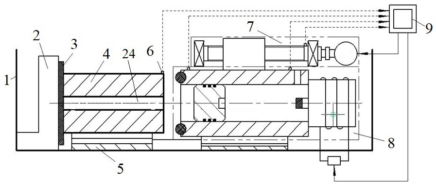
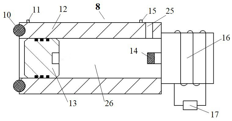
[0023] Such as figure 1 As shown, a pressure alternating microporous inner surface cavitation shot blasting equipment according to the present invention includes an oil tank 1 filled with oil. In the oil tank 1, a positioning device and a magnetic piston moving device 8 are installed, and the positioning device and the magnetic piston moving device 8 are installed facing each other left and right. Among them, the positioning device is used to fix the workpiece 4. The positioning device includes an L-shaped baffle 2, a gasket 3 and a composite V-shaped block 5. The L-shaped baffle 2 and the fuel tank 1 are fixedly connected together by screws. Below the right side of the baffle plate 2 is a composite V-shaped block 5, and the composite V-shaped block 5 is fixed on the bottom wall of the fuel tank 1 by screws. The workpiece 4 is placed on the composite V-shaped block 5, and the workpiece 4 is horizontally placed on the left and right sides, and the microhole 24 is opened on it,...


PUM

PropertyMeasurementUnit
diameteraaaaaaaaaa

Abstract

The invention discloses pressure-alternated microhole inner surface cavitation and shot blasting equipment and a working method. A positioning device and a magnetic piston motion device arranged faceto face left and right are arranged in an oil tank; an L-shaped baffle plate of the positioning device is fixedly connected with the oil tank; a composite V-shaped block fixedly connected to the bottom wall of the oil tank is arranged under the right side of the L-shaped baffle plate; left and right horizontal workpieces are placed on the composite V-shaped block; the center axis of a cylinder ofthe magnetic piston motion device is collinear with the center axes of microholes; a piston is arranged in a center hole of the cylinder; a sealing cavity can be formed between the microholes and thecenter hole of the cylinder; the right end surface of the cylinder is fixedly connected with an electromagnet; a coil is wound on the electromagnet; two ends of the coil are connected with reversing switches; a driving device is above the magnetic piston motion device; a motor of the driving device can drive a lead screw to rotate; a slide block is matched with the lead screw through a thread; theslide block is fixedly connected with the cylinder; and the volume of liquid in the sealing chamber is continuously changed through a reciprocating motion of the piston for shot blasting reinforcement of the inner surfaces of the microholes so as to achieve high efficiency.

Description

technical field [0001] The invention belongs to the component surface strengthening treatment technology in the field of mechanical manufacturing, in particular to shot peening strengthening equipment suitable for the micropore inner surface of workpieces. Background technique [0002] At present, the parts produced and processed are more precise, lightweight, and have diversified structures, which largely meet the requirements of different fields, especially in high-precision technology-intensive industries such as aerospace and automobiles. Micro-holes have become a common structure in parts. For example, the heat dissipation micro-holes of aero-engine blades, the micro-holes of automobile exhaust pipes, and the micro-holes of molds, etc.; but during the use of workpieces with micro-holes, stress concentration often occurs on the inner surface, and fatigue cracks appear on the surface. It greatly affects the service life of parts. For this reason, various surface strengthe...

Claims


Application Information

Patent Timeline
Patent Type & Authority Patents(China)
IPC IPC(8): C21D7/06
CPCC21D7/06
Inventor 李瑞涛陈维国王匀郭玉琴李品陈月亮蒋鹏赟刘宏
Owner JIANGSU UNIV
Learn More