
Proton exchange membrane water electrolysis cell
A technology of proton exchange membrane and water electrolyzer, applied in the direction of electrolysis components, electrolysis process, diaphragm, etc., can solve the problems of high manufacturing cost, bulky, difficult processing, etc., reduce processing difficulty and cost, improve contact effect, improve The effect of electrolytic efficiency
- Summary
- Abstract
- Description
- Claims
- Application Information
AI Technical Summary
Problems solved by technology
Method used
Image

Examples
Embodiment Construction
[0030] In order to have a clearer understanding of the technical features, purposes and effects of the present invention, the specific implementation manners of the present invention will now be described in detail with reference to the accompanying drawings.
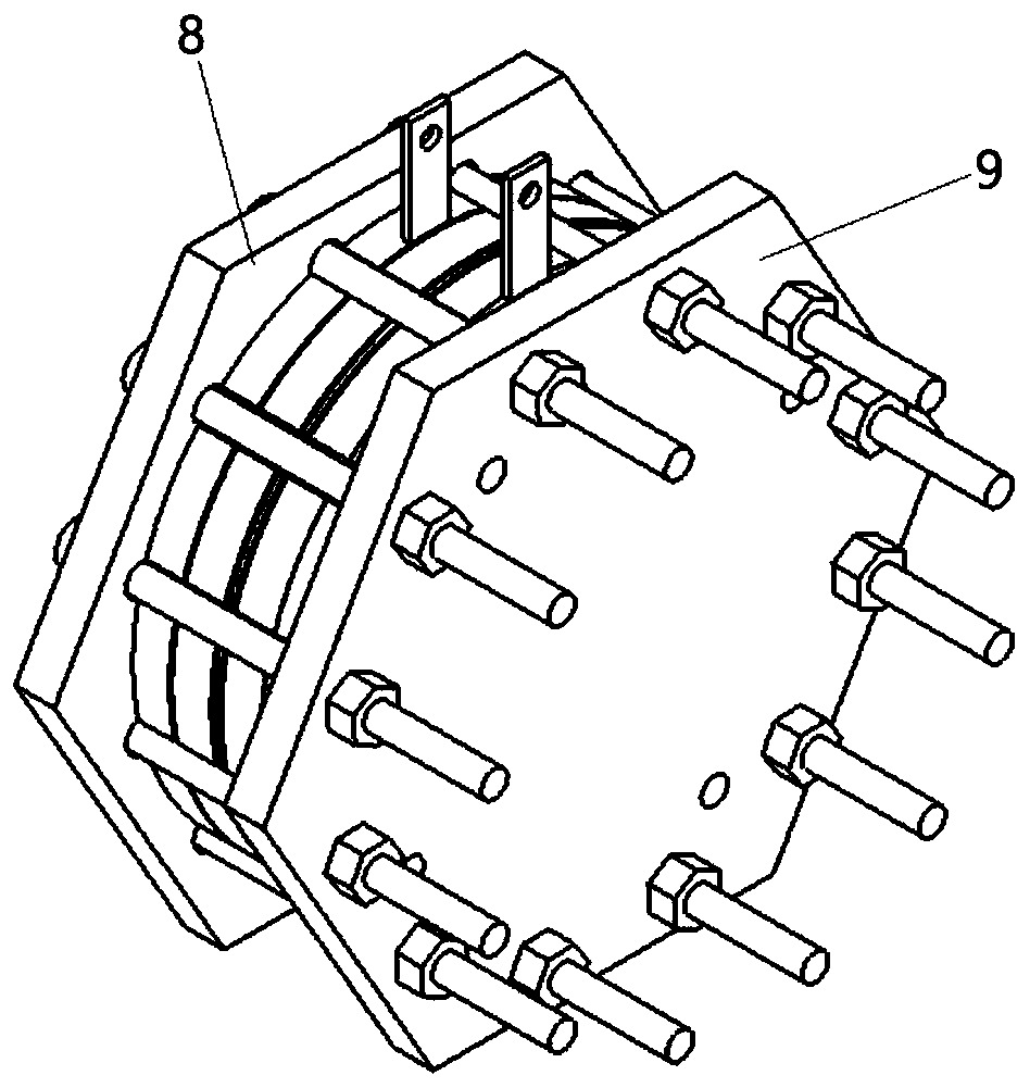
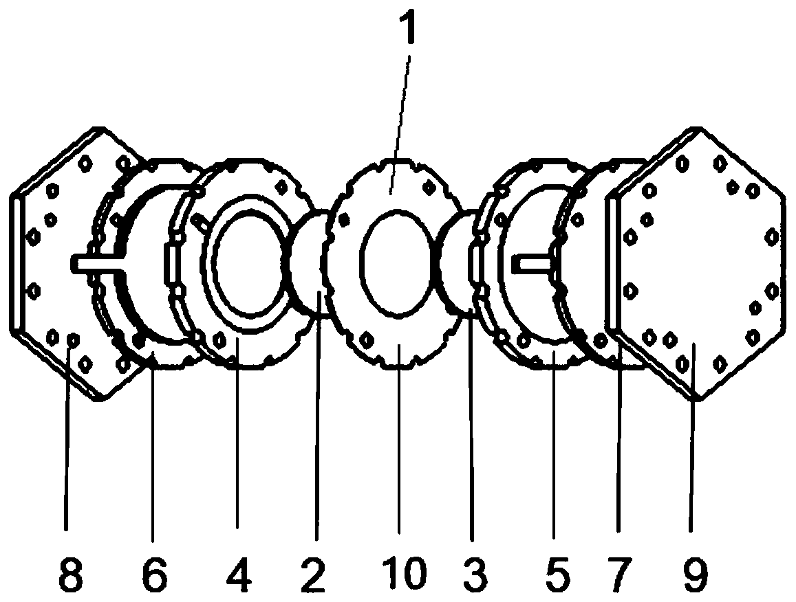
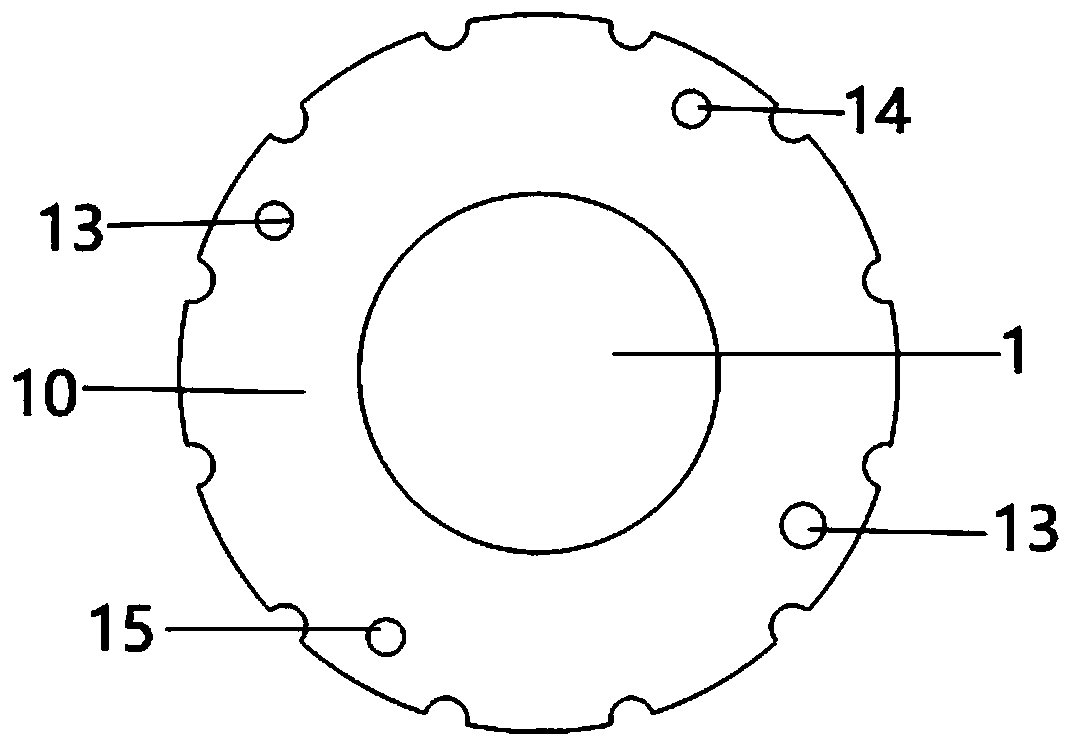
[0031] Such as Figure 1-7 As shown, the proton exchange membrane 1 water electrolyzer of the present invention comprises proton exchange membrane 1, cathode catalytic layer, anode catalytic layer, cathode diffusion layer 2, anode diffusion layer 3, cathode flow field plate 4, anode flow field plate 5, left Epoxy resin plate 6 , right epoxy resin plate 7 , left end plate 8 and right end plate 9 . The left end plate 8, the left epoxy resin plate 6, the cathode flow field plate 4, the middle substrate 10, the anode field flow plate, the right epoxy resin plate 7 and the right end plate 9 are fixedly connected, and are provided with communicating gas-liquid channels.
[0032] The cathode catalytic layer and the anode cata...
PUM
 Abstract
Description
Claims
Application Information