Impeller dynamic balance de-weight automatic turning device and method

A turning device and impeller technology, applied in the direction of grinding drive device, static/dynamic balance test, measuring device, etc., can solve problems such as deformation and unbalanced quality, difficulty in dynamic balance and weight removal, and hidden dangers of operation safety, etc., to achieve Avoid the rotation of the disc impeller, the effect of de-weighting work is good, and the effect of reducing work intensity

Inactive Publication Date: 2019-08-16
SHENYANG TURBO MASCH CORP
View PDF9 Cites 4 Cited by
  • Summary
  • Abstract
  • Description
  • Claims
  • Application Information

AI Technical Summary

Problems solved by technology

However, in the actual situation, due to the uneven distribution of the mass density of the impeller during the manufacturing process, the asymmetrical position of the blade assembly, and deformation after heat treatment, the unbalanced mass during dynamic balancing is too large, and sometimes the unbalanced amount reaches several kilograms.
In this way, the work of dynamic balancing and de-weighting becomes very difficult, the operation is complicated, time-consuming and labor-intensive, and brings a lot of workload to the balancing workers. At present, the dynamic balancing and de-weighting of the impeller usually requires one person to operate the grinder. One person turns the impeller, which takes time and effort when the unbalance is large, and there is a huge hidden danger in operation safety
Therefore, how to quickly remove the large unbalance of the impeller to meet the technical requirements has become a major technical barrier in the balancing work, seriously affecting the rotor balancing efficiency

Method used


Image

  • Impeller dynamic balance de-weight automatic turning device and method
  • Impeller dynamic balance de-weight automatic turning device and method

Examples


Embodiment Construction

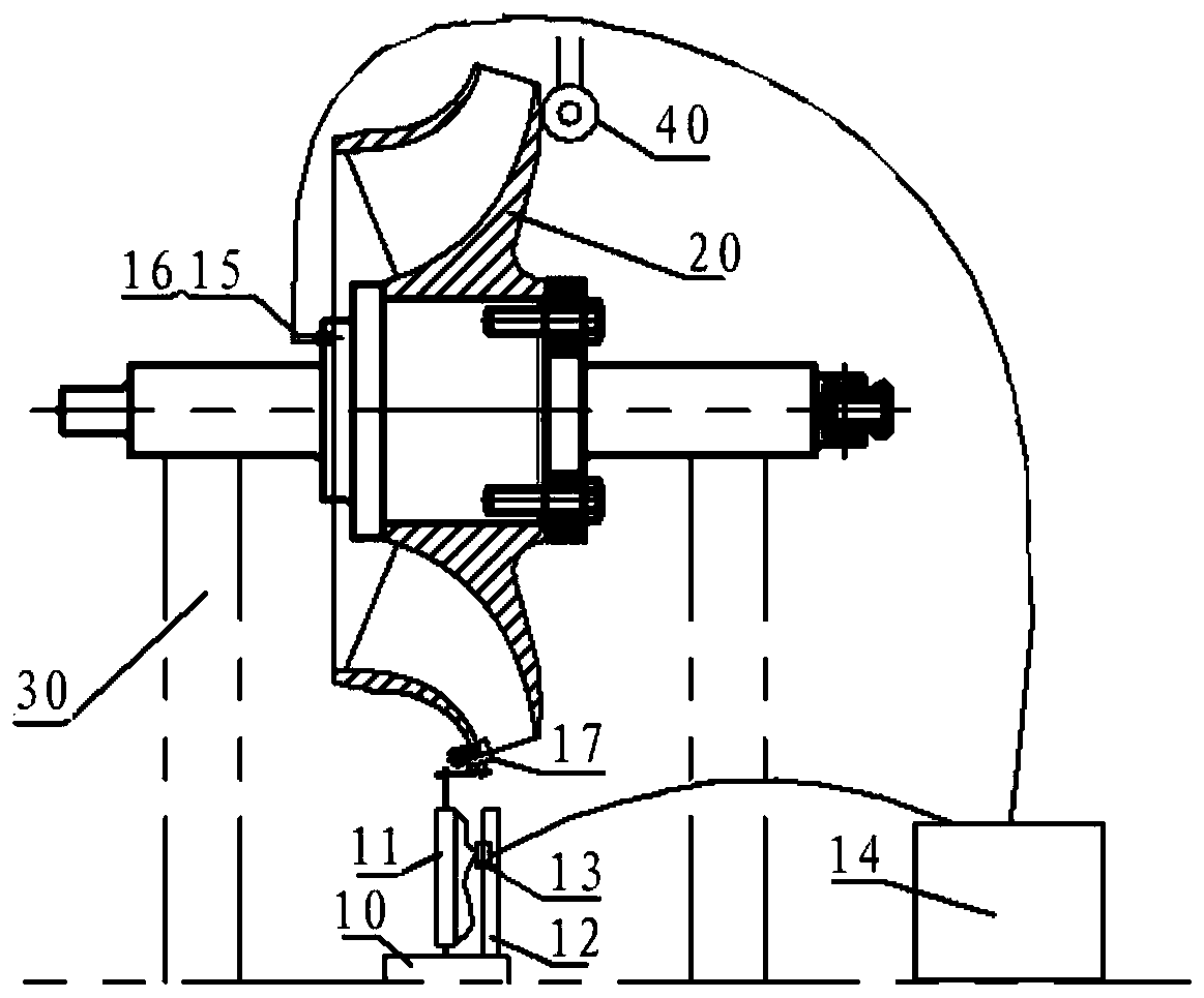
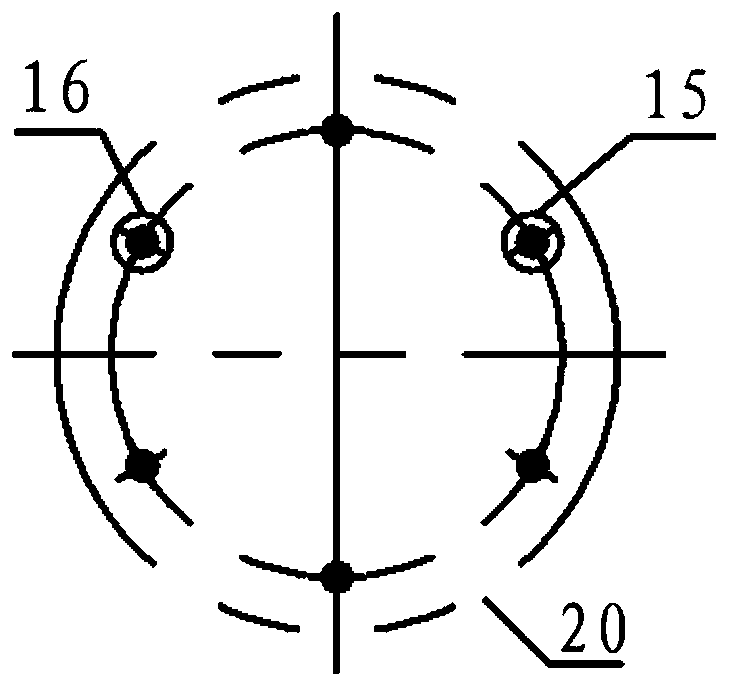
[0019] see figure 1 , an impeller dynamic balance de-weighting automatic turning device provided in an embodiment of the present invention includes a base 10, a cylinder 11, a cylinder bracket 12, a universal clamp 17, an electric control device 14, a first non-contact probe 15, a second non-contact probe Contact probe 16, and probe support (probe support figure 1 not shown). Wherein, the impeller 20 is fixed on the dynamic balancing machine 30 through the axles on both sides, the base 10 is fixedly arranged on the workbench of the dynamic balancing machine 30, the universal clamp 17 is fixed at the outlet position of the impeller 20, and one end of the cylinder 11 is hinged on the base 10, the other end is connected with Vientiane fixture 17 through hinges, and the two ends of cylinder 11 are respectively hinged with base 10 and Vientiane fixture 17, which can ensure that cylinder 11 swings freely during motion. At the same time, in order to avoid cylinder 11 topple over, cy...


PUM


Abstract

The invention provides an impeller dynamic balance de-weight automatic turning device. The device comprises a base, a universal clamp fixed at an outlet position of an impeller, a cylinder, a cylindersupport arranged on the base and used for supporting the cylinder, and a first non-contact probe and a second non-contact probe arranged at the other side of the impeller opposite to an starting point position and a terminal position of a de-weight angle range of the impeller, one end of the cylinder is hinged to the base, the other end of the cylinder is hinged to the universal clamp, the cylinder support is provided with a solenoid directional valve connected with the cylinder and used for controlling reciprocating operation of the cylinder, and the first non-contact probe, the second non-contact probe and the solenoid directional valve are separately connected with an electrical control device. The invention also provides an impeller dynamic balance de-weight automatic turning method.According to the impeller dynamic balance de-weight automatic turning device and method, the de-weight efficiency is high, and the operation is convenient.

Description

technical field [0001] The invention relates to the technical field of centrifugal compressor dynamic balance, in particular to an impeller dynamic balance de-weighting automatic barring device and method. . Background technique [0002] In petrochemical, oil refining and other equipment, centrifugal drums and compressors are one of the core equipment, and with the continuous increase of the processing capacity of my country's oil refining equipment, the volume of the impeller and rotor of the compressor is also increasing, and the rotor assembly The final weight has reached tens of tons, or even more. However, in the actual situation, due to the uneven distribution of the mass density of the impeller during the manufacturing process, the asymmetrical position of the blade assembly, and deformation after heat treatment, the unbalanced mass during dynamic balancing is too large, and sometimes the unbalanced amount reaches several kilograms. In this way, the work of dynamic b...

Claims


Application Information

Patent Timeline
Patent Type & Authority Applications(China)
IPC IPC(8): G01M1/34B24B19/14B24B47/16
CPCB24B19/14B24B47/16G01M1/34
Inventor 周顺新刘巍王福新关欣蒋传杰乔侽邵帅王思倩于洋刘百宁王俊富永亮张帝张原平张威张淇柳鹏王宝华
Owner SHENYANG TURBO MASCH CORP
Why Eureka
Try Eureka