Novel automatic lifting nitrogen blowing instrument

A technology of automatic lifting and nitrogen blowing instrument, used in instruments, scientific instruments, sampling and other directions, can solve the problems of inconvenient, inconvenient, artificial loosening of the height adjustment of the blowing pipe, saving labor costs, simple structure, and stable lifting control. Effect

Pending Publication Date: 2019-08-16
中山市农产品质量监督检验所
View PDF3 Cites 2 Cited by
  • Summary
  • Abstract
  • Description
  • Claims
  • Application Information

AI Technical Summary

Problems solved by technology

At present, it is inconvenient to adjust the height of the blowing pipe of the nitrogen blowing instrument. The gas supply device is fixed on the bracket. When the height of the gas supply device needs to be adjusted, it is necessary to manually loosen the fixing point, and then adjust the height, which is very inconvenient.

Method used


Image

  • Novel automatic lifting nitrogen blowing instrument

Examples


Embodiment 1

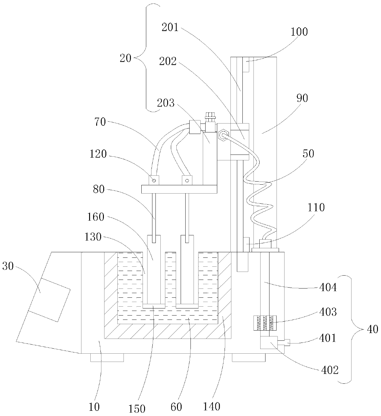
[0026] refer to figure 1 , in the embodiment of the present invention, a new type of automatic lifting nitrogen blowing instrument includes a base 1, a control panel 30 is installed on the side of the base 1, the control panel 30 is electrically connected to the electric slider 202 through a wire, and the control panel 30 sends out Instructions control the sliding of the electric slider 202. The upper end of the base 1 is provided with a heating pool 60, the right side of the base 1 is equipped with a preheating device 40, and the right side of the upper end of the base 1 is connected with a lifting device 20 through a bracket 90. The device 20 includes an electric slider 202, a linear guide rail 201 and a lifting plate 203. The electric slider 202 is sleeved on the linear guide rail 201 and moves longitudinally along the linear guide rail 201. The electric slider 202 is connected with the lifting plate 203. The lifting plate 203 is also provided with a nitrogen blowpipe 70 an...

Embodiment 2

[0033] In another embodiment of the present invention, the difference between this embodiment and the above-mentioned embodiment is that the heating pool 60 is made of high temperature resistant glass material, and a groove 130 is opened in the heating pool 60 for heating Pool 60 periphery is provided with heat insulation layer 140, and described groove 130 interior is provided with test tube 160, and groove 130 bottom is provided with gasket 150, and this gasket 140 is used for preventing the test tube 160 in groove 130 from contacting with the bottom of groove 130. Collision damage, its function of heating pool 60 is exactly to fix test tube 160 and conduct heat, and heating pool 60 adopts high temperature resistant glass material to be convenient to observe the change of the sample in test tube 160 simultaneously; Heat from the heating pool 60 is dissipated.

[0034]The working principle of the present invention is: when in use, the sample to be concentrated is first packed...


PUM


Abstract

The invention discloses a novel automatic lifting nitrogen blowing instrument, and belongs to technical field of the sample concentration device. The nitrogen blowing instrument comprises a base, a heating bath is arranged in an upper end of the base, a pre-heating device is arranged in a right side of the base, and a right side of the upper end of the base is connected with a lifting device through a bracket; the lifting device comprises an electric sliding block, a linear guide rail and a lifting plate; the electric sliding block is sleeved on the linear guide rail and longitudinal moves along the linear guide rail; the electric sliding block is connected with the lifting plate, and a nitrogen blowing pipe and a blowing needle are arranged on the lifting plate. The nitrogen blowing instrument disclosed by the invention is simple in structure and reasonable in design; the electric height regulation is realized by improving the structure; the precise and stable lifting control is realized through the automatic lifting device; the working efficiency is improved, and the manpower cost is saved; and the nitrogen blowing instrument is suitable for the sample with is small in sample size and needs batch nitrogen blowing.

Description

technical field [0001] The invention relates to the technical field of sample concentration devices, in particular to a novel automatic lifting nitrogen blowing instrument. Background technique [0002] Sample concentration is a problem that every chemical laboratory must deal with. In the past, a rotary evaporator was mainly used for concentration, but the disadvantages of using a rotary evaporator for concentration are obvious: the concentration speed is slow, the operation is troublesome, and it is especially not suitable for small samples. In this case, the nitrogen blowing instrument came into being. It not only solves all the shortcomings of the rotary evaporator, but is especially suitable for a small number of samples, and it is even more suitable for samples that cannot be heated or even need to be cooled and concentrated. It can only be concentrated with a nitrogen blower, therefore, a nitrogen blower has become a must-have instrument for every chemical laboratory...

Claims


Application Information

Patent Timeline
Patent Type & Authority Applications(China)
IPC IPC(8): G01N1/40G01N1/44
CPCG01N1/4022G01N1/44
Inventor 冯敏铃李盛安黄晓声刘铭扬张定煌周秀莹邹学仁
Owner 中山市农产品质量监督检验所
Why Eureka
Try Eureka