Cervical spine injury transfer fixator

A fixator and cervical spine technology, applied in the field of cervical spine injury transfer fixator, can solve the problems of poor neck fixation effect of patients, aggravate the patient's condition, and discomfort of the patient, and achieve the purpose of promoting air circulation, improving comfort, and promoting the neck. The effect of blood circulation

Inactive Publication Date: 2019-08-20
贾如松
View PDF14 Cites 6 Cited by
  • Summary
  • Abstract
  • Description
  • Claims
  • Application Information

AI Technical Summary

Problems solved by technology

[0003] When the patient's cervical spine is injured, timely treatment is required. The cervical spine is fixed and then transferred to the treatment department of the hospital for further treatment. During the transfer, the patient's cervical spine must be fixed to avoid large damage during transfer. However

Method used


Image

  • Cervical spine injury transfer fixator
  • Cervical spine injury transfer fixator
  • Cervical spine injury transfer fixator

Examples


Embodiment 1

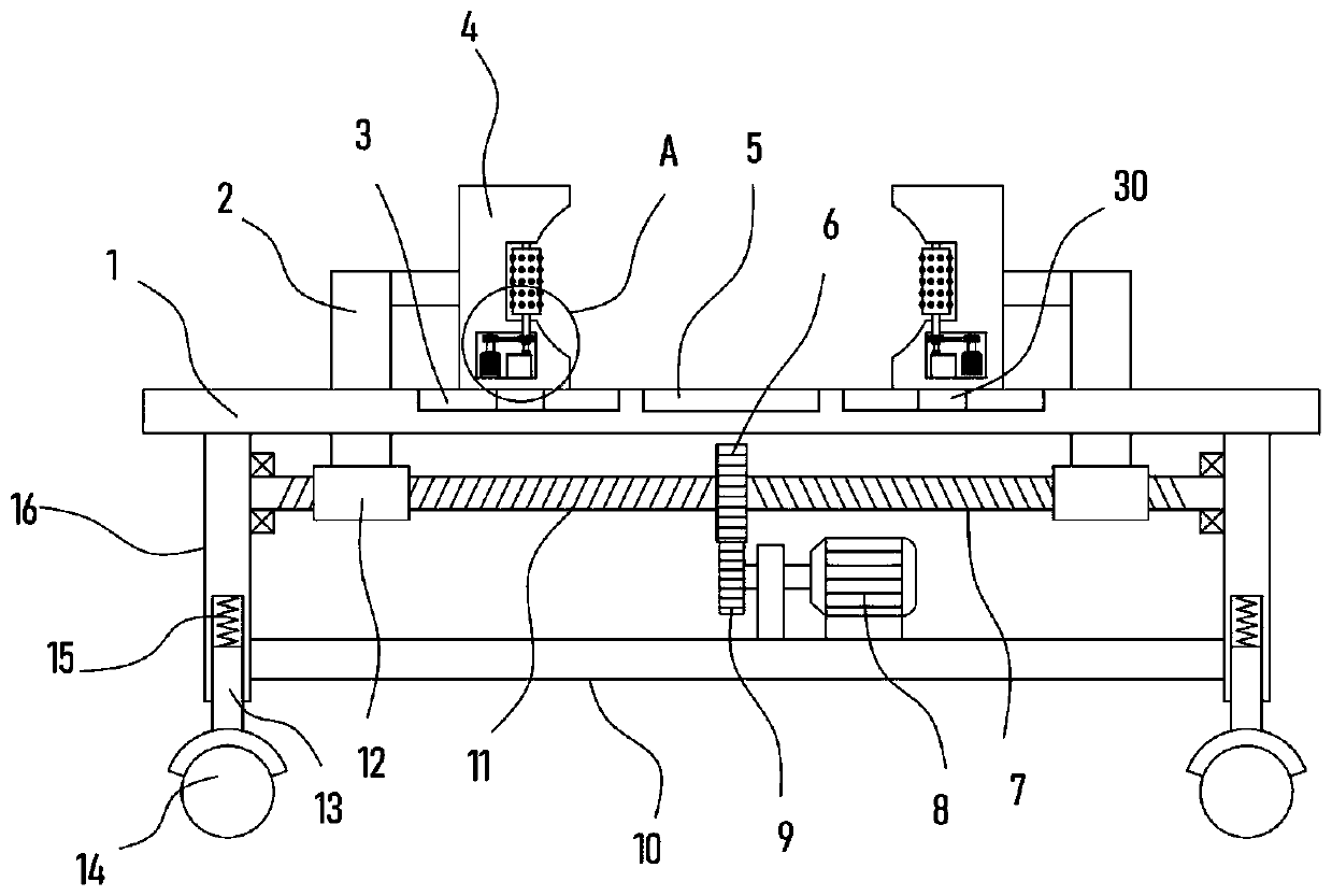
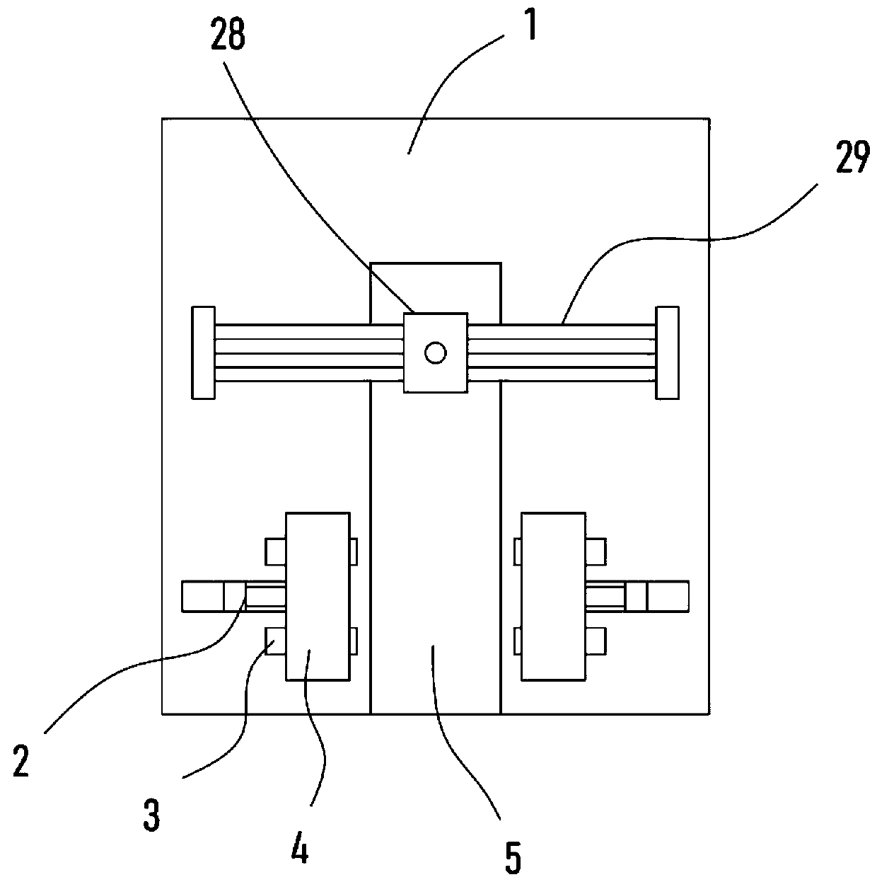
[0021] see Figure 1-3 , a cervical spine injury transfer fixator, comprising a deck board 1, a patient with cervical spine damage lies on the deck board 1, a plurality of support legs 16 are fixed on the bottom of the deck board 1, and universal wheels 14 are arranged at the bottom of the support legs 16, and the The universal wheel 14 is used to move the device as a whole, so as to realize the mobile transfer of cervical patients.

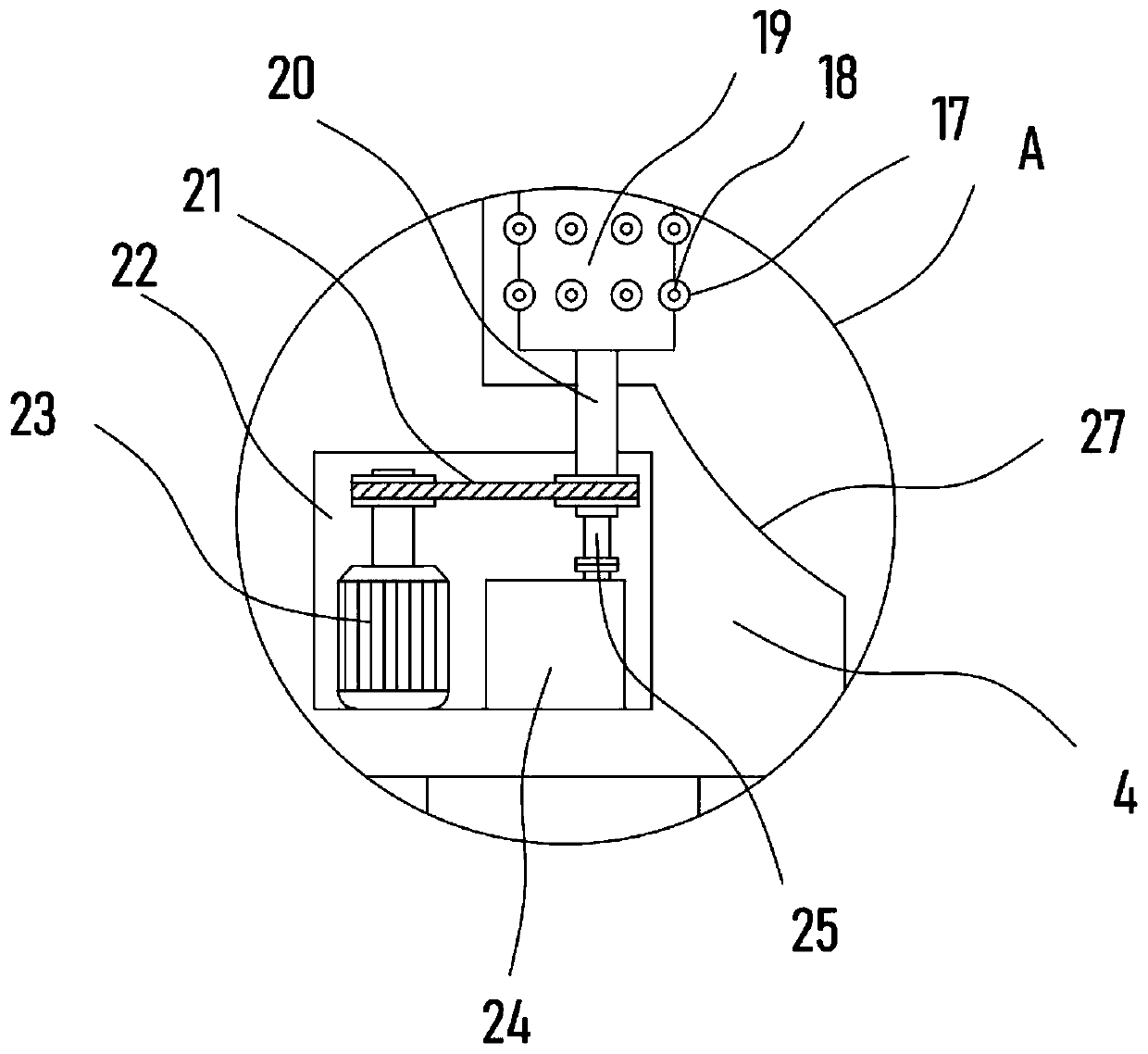
[0022] Two clamping blocks 4 oppositely arranged are slidably installed on the recliner 1, and the two clamping blocks 4 are driven to slide through the adjustment mechanism. The opposite sides of the two clamping blocks 4 are provided with clamping arc grooves 27, and the two clamping blocks 4 are provided with clamping arc grooves 27. The holding block 4 is clamped from both sides of the patient's neck to fix the neck, and the clamping arc groove 27 is close to the patient's neck to achieve the clamping effect.

[0023] The clamping block 4 is...

Embodiment 2

[0026] In order to clamp the patient's neck conveniently and realize fast clamping and fixing of the cervical spine, on the basis of Embodiment 1, the adjustment mechanism includes coaxially fixed threaded rods I7 and threaded rods II11 with opposite helical directions, threaded rods I7 and The threaded sleeves on the threaded rod II11 are fixed with a threaded sleeve block 12, and the connecting rod 2 is fixedly connected between the threaded sleeve block 12 and the clamping block 4. A servomotor 8 is fixed horizontally, and the output shaft of the servomotor 8 is coaxially fixed with a driving gear 9, and the driving gear 9 is meshed with a driven gear 6 sleeved and fixed on the threaded rod II11 or the threaded rod I7.

[0027] Through the above settings, the servo motor 8 can drive the driving gear 9 to rotate, and the driving gear 9 drives the threaded rod II11 to rotate together with the threaded rod I7 through the driven gear 6 meshed with it, and the threaded rod I7 and...


PUM


Abstract

The invention discloses a cervical spine injury transfer fixator and relates to the technical field of medical devices. The cervical spine injury transfer fixator comprises a lying board, wherein a plurality of supporting legs are fixed at the bottom of the lying board; universal wheels are arranged at bottoms of the supporting legs; two clamping blocks are oppositely arranged on the lying board in a sliding manner; a motor is arranged in a cavity; and a hollow shaft is coaxially fixed on a drum through coaxial fixed connection of a belt pulley mechanism and the output shaft of the motor. According to the cervical spine injury transfer fixator, opposite motion of the clamping blocks can be realized by adjusting an adjustment mechanism, the neck of a patient lying on the lying board can beclamped and fixed, an effect of fixing the cervical spine of the patient in a transferring process is ensured, and the occurrence of substantial shaking is avoided; massage bumps are driven to massagethe neck by rotation of the drum, and blood circulation of the neck is promoted; airflow can be jetted through vent holes in the massage bumps, air circulation around the neck can be promoted, and the comfortable degree of the neck in the clamping and fixing process can be greatly promoted.

Description

technical field [0001] The invention relates to the technical field of medical devices, in particular to a transfer fixator for cervical spine injuries. Background technique [0002] Cervical vertebrae refer to the cervical vertebrae, which are located below the head and above the thoracic vertebrae. They are located in the cervical spine. There are 7 pieces in total, surrounding the cervical spinal cord and its meninges. Connected by intervertebral discs and ligaments, forming a lordotic physiological curvature. The cervical spine is characterized by a small, oval-shaped vertebral body. There is a transverse process hole on the transverse process, through which the vertebral artery and vertebral vein pass; the spinous process is short and divided. Fork; the joints of the upper and lower articular processes are approximately horizontal, so that the neck can move flexibly. The upper and lower notches of adjacent vertebrae form the intervertebral foramen, through which spinal ...

Claims


Application Information

Patent Timeline
IPC IPC(8): A61G1/02A61G1/04A61F5/05A61H7/00
CPCA61F5/05A61G1/02A61G1/04A61H7/007A61H2201/1207A61H2205/04
Inventor 贾如松
Owner 贾如松
Why Eureka
Try Eureka