
Camera with electrostatic dust removal function

An electrostatic dust removal and camera technology, which is applied in the direction of cameras, electrostatic cleaning, camera body, etc., can solve the problems of aggravating lens wear, affecting lens imaging, and spending more time, so as to improve dust removal efficiency and simple operation method , the effect of shortening the cleaning time

Inactive Publication Date: 2019-08-20
李峥炜
View PDF0 Cites 6 Cited by
  • Summary
  • Abstract
  • Description
  • Claims
  • Application Information

AI Technical Summary

Problems solved by technology

[0002] The camera includes a lens group, darkroom, imaging medium and imaging control structure. It is a relatively sophisticated instrument that needs to be carefully protected during use; but dust in the air is everywhere, and it is easy to enter fine dust during use. ;When dust adheres to the surface of the lens, it will affect the imaging of the lens and cause dark spots in the photo; if it is not cleaned in time, it will easily increase the wear of the lens, and even cause the camera components to be stuck, causing irreparable damage to the camera; , the surface of the lens is coated and needs to be touched and cleaned gently. Due to the secretion of oil on the skin of the fingers, it cannot be touched directly by the fingers when cleaning, and a special air blower or cleaning brush is often required. Therefore, the cleaning work requires It takes a lot of time; if there is dust adhesion during normal shooting, the photographer has to stop the normal work and clean the lens, which will seriously affect the normal shooting work

Method used


Image

  • Camera with electrostatic dust removal function
  • Camera with electrostatic dust removal function

Examples


Embodiment

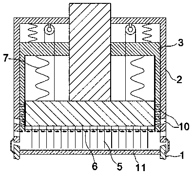
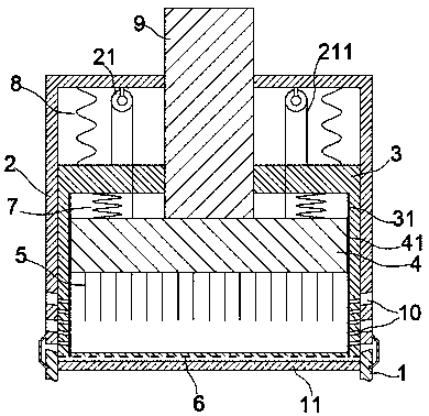
[0022] exist figure 1 , figure 2 In the shown embodiment, the electrostatic dust removal camera includes a camera body, and a lens cover is detachably arranged on the lens 1 of the body;

[0023] The lens cover includes a cover body 2 that can be matched with the lens 1, and the cover body 2 and the lens 1 can be matched through a snap fit, or can be screwed and matched through a screw thread or a screw groove, or matched through magnetic adsorption; A piston frame 3 is slidably arranged in the cover body 2, and the outer wall of the piston frame 3 is in sliding contact with the inner wall of the cover body 2 in close fit;

[0024] A piston plate 4 is slidably arranged inside the piston frame 3, a volatile electronic friction layer 31 is arranged on the inner sidewall of the piston frame 3, and an easy-to-get electronic friction layer 41 is arranged on the outer sidewall of the piston plate 4. The electronic friction layer 41 and the volatile electronic friction layer 31 ca...


PUM


Abstract

The invention relates to a camera with the electrostatic dust removal function. The camera with the electrostatic dust removal function comprises a body and a lens shade. The lens shade comprises a shade body. A piston frame is arranged in the shade body in a sliding manner. A piston plate is arranged in the piston frame in a sliding manner. An electron-loss-prone friction layer and an electron-gain-prone friction layer are arranged between the piston frame and the piston plate. Spray points are arranged on the lower surface of the piston plate. An electrostatic plate is arranged on the lowersurface of the piston frame. A pulley block is arranged on a top plate of the shade body. A pulling rope is installed in the pulley block. The pulling rope is fixed to the piston frame and the pistonplate. Reset tension springs are arranged between an upper plate of the piston frame and the upper surface of the piston plate. A push rod is further arranged on the upper surface of the piston plate.Air guiding holes are formed in the lower parts of side plates of the shade body and side plates of the piston frame. The camera with the electrostatic dust removal function is novel in structure, unique in principle, and convenient and quick to operate, and the time for removing dust can be effectively shortened so that a lens can quickly become bright and clean again.

Description

technical field [0001] The invention relates to a camera, in particular to a camera for conveniently removing lens dust. Background technique [0002] The camera includes a lens group, darkroom, imaging medium and imaging control structure. It is a relatively sophisticated instrument that needs to be carefully protected during use; but dust in the air is everywhere, and it is easy to enter fine dust during use. ;When dust adheres to the surface of the lens, it will affect the imaging of the lens and cause dark spots in the photo; if it is not cleaned in time, it will easily increase the wear of the lens, and even cause the camera components to be stuck, causing irreparable damage to the camera; , the surface of the lens is coated and needs to be touched and cleaned gently. Due to the secretion of oil on the skin of the fingers, it cannot be touched directly by the fingers when cleaning, and a special air blower or cleaning brush is often required. Therefore, the cleaning wor...

Claims


Application Information

Patent Timeline
IPC IPC(8): B08B6/00G03B17/56
CPCB08B6/00G03B17/56
Inventor 李峥炜
Owner 李峥炜
Learn More