
Communication wire harness type conversion module unit and unit box

A conversion module and module box technology, which is applied in the direction of optical components, light guides, optics, etc., can solve the problems of poor operation and maintenance convenience of module units, easy and fast installation of module unit boxes, increase and decrease of lines, low deployment efficiency and other problems , to achieve the effect of convenient unit combination and independent use, fast and efficient deployment, and convenient maintenance

Active Publication Date: 2019-08-20
NINGBO YUDA COMM TECH
View PDF7 Cites 2 Cited by
  • Summary
  • Abstract
  • Description
  • Claims
  • Application Information

AI Technical Summary

Problems solved by technology

[0003] In order to overcome the above-mentioned deficiencies, the purpose of the present invention is to provide a communication wiring type conversion module unit and unit box to the field, so that it can solve the problems of easy and fast installation of the module unit box in existing similar products, and insufficient safety protection of internal devices. technical problems such as inconvenient replacement and replacement of components, poor operation and maintenance convenience of module units, increase and decrease of lines, and low deployment efficiency

Method used


Image

  • Communication wire harness type conversion module unit and unit box
  • Communication wire harness type conversion module unit and unit box
  • Communication wire harness type conversion module unit and unit box

Examples


Embodiment Construction

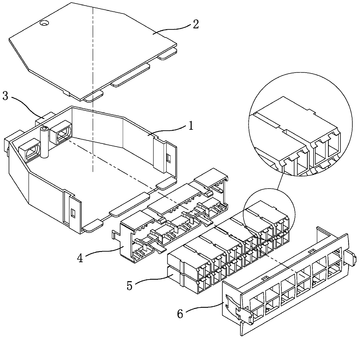
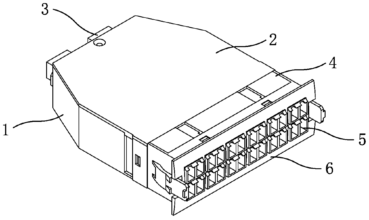
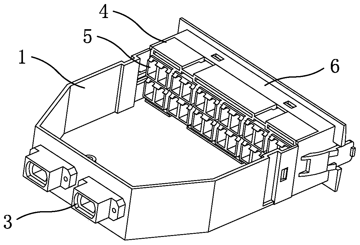
[0031] Now in conjunction with the accompanying drawings, the structure and use of the present invention will be further described. Such as Figure 1-Figure 6 As shown, the module unit box is a new type of optical fiber protection box structure in which an integrated adapter is converted into an independent adapter. The module box body 1 is a cavity box body composed of a rectangular front end and a trapezoidal rear end. The top and front end of the module box body are one There is an opening on the side, and the cover plate 2 is buckled correspondingly to the top opening of the module box body. Evenly distributed optical fiber independent adapters 5 are arranged inside the insert block 4, and the optical fiber independent adapters are fixed between the insert block and the panel, and the insert block is fastened to the panel As a whole, the insert block is fastened and fixed to the opening on one side of the front end formed by the module box body and the cover plate. Its sp...


PUM


Abstract

The invention relates to a communication wire harness type conversion module unit and a communication wire harness type conversion module unit box. The invention mainly aims to solve the technical problems of poor structural design and inconvenient maintenance and assembly and disassembly of the module units and unit boxes of existing products similar to the products of the module unit and the unit box of the invention. The communication wire harness type conversion module unit box is characterized in that block barbs at two sides of the edge of the rear end of the insertion block of the module unit box are buckled to the block hook holes of a module box body; the plate barbs of the insertion block are buckled to plate hook holes in the upper edge and lower edge of a panel; the module boxbody, a cover plate, the insertion block and the panel are plastic parts; the module unit box is fixed in the module through hole of a front panel in the module unit; a drawing box body is arranged inthe fixing box body of the module unit; a rear cover is arranged at one side of the top of the rear end of the fixing box body; the drawing box body and the front panel are connected into an integrated body; mounting plates are arranged at two sides of the fixing box body; a large kidney-shaped hole is formed in the bent front edge plate of the front panel; a wire winding column is installed; a door is connected with the edge of the front edge plate of the front panel through a hinge; the fixing box body, the rear cover, the drawing box body, the front panel and the mounting plates are steelplates which are made of plates by means of punching.

Description

technical field [0001] The invention relates to communication wiring equipment, which is a communication wiring conversion module unit and a unit box. Background technique [0002] The conversion module unit is a main component used for the connection of optical fiber in and out of the optical fiber distribution frame. The optical fiber distribution frame is a wiring connection device used between optical cables and optical communication equipment or between optical communication equipment. It is mainly used for In the optical fiber communication system, the termination and distribution of the trunk optical cable at the central office can conveniently realize the connection, distribution and scheduling of optical fiber lines. Its main component is the distribution unit, and the conversion module unit is installed in the module through hole of the distribution unit. Such existing conversion module units for optical cable distribution frames are disclosed in Chinese patent doc...

Claims


Application Information

Patent Timeline
Patent Type & Authority Applications(China)
IPC IPC(8): G02B6/44G02B6/38
CPCG02B6/4452G02B6/3825G02B6/3814
Inventor 徐坚荣
Owner NINGBO YUDA COMM TECH
Learn More