Multi-directional laser vision tracking device and tracking and controlling method thereof

A visual tracking and multi-directional technology, applied in auxiliary devices, manufacturing tools, auxiliary welding equipment, etc., can solve the problems of large parts, unrecognizable, tracking and welding, complex structures, etc., to achieve small overall structure, reduce spatter and interference situation, the effect of increasing the welding rate

Active Publication Date: 2019-08-23
芜湖行健智能机器人有限公司 +1
View PDF7 Cites 3 Cited by
  • Summary
  • Abstract
  • Description
  • Claims
  • Application Information

AI Technical Summary

Problems solved by technology

[0002] At present, the visual recognition weld seam automatic tracking welding has been applied to heavy machinery industries such as shipbuilding, ocean engineering, steel structure bridges, steel structure buildings, containers, chemical machinery, and lifting machinery. Large size, complex structure, and the structural limitations of the visual tracking equipment itself, resulting in interference between the welding robot and the welded part during the welding process from flat fillet welding to vertical fillet welding, especially at the beginning and end of the weld, resulting in some positions being unrecognizable , tracking and welding

Method used


Image

  • Multi-directional laser vision tracking device and tracking and controlling method thereof
  • Multi-directional laser vision tracking device and tracking and controlling method thereof

Examples


Embodiment Construction

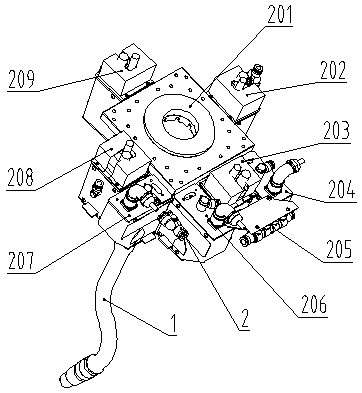
[0012] like figure 1 As shown, a multi-directional laser vision tracking device includes a special-shaped welding torch 1, a laser vision sensor 2 and a computer control system; the laser vision sensor 2 is installed at the end of the manipulator, and the special-shaped welding torch 1 is arranged at the lower end of the center of the laser vision sensor 2; The laser vision sensor 2 includes a flange frame 201, a first camera 202, a fourth camera 203, a third laser 204, an integrated pipeline 205, a first laser 206, a second laser 207, a third camera 208, and a second camera 209. The flange frame 201 is connected to the manipulator, the first camera 202 is arranged on the right side of the flange frame 201 , the second camera 209 is arranged on the front side of the flange frame 201 , and the third camera 208 is arranged on the left side of the flange frame 201 , the fourth camera 203 is arranged on the rear side of the flange frame 201, the first laser 206 is arranged on the ...


PUM


Abstract

The invention discloses a multi-direction laser vision tracking device and a tracking and controlling method thereof. The device comprises a laser vision sensor, a special-shaped welding gun and a computer control system, wherein the laser vision sensor is arranged at the tail end of a mechanical arm, and the special-shaped welding gun is arranged at the lower end of the center of the laser visionsensor. The laser vision sensor comprises a flange frame, four cameras, three lasers, an integrated pipeline. The four cameras are uniformly arranged around the upper end of the welding gun, whereinthe first camera and the third camera are arranged in a paring mode with the first laser and the third laser on the inclined opposite sides of the flange frame for measuring and tracking weld joints in the front, in the rear and in the side, and the fourth camera is arranged in the other direction for observing and monitoring the weld joints. According to the multi-direction laser vision trackingdevice and the tracking and controlling method thereof, the measuring and tracking of the crossed welding joints can be achieved, thus realizing the switching and tracking of the welding joints in thelongitudinal direction, the transverse direction and the vertical direction; in addition, the welding method solves the problems that due to the fact that a steel plate well-shaped structure, a corrugated plate and other complex structures are limited in space and easy to interfere with the starting end and the tail end,

Description

technical field [0001] The invention relates to welding equipment, in particular to a multi-directional laser vision tracking device and a method for tracking and controlling the same. Background technique [0002] At present, automatic tracking welding of visual recognition welds has been applied to heavy machinery industries such as shipbuilding, marine engineering, steel structure bridges, steel structure buildings, containers, chemical machinery and hoisting machinery. Large and complex structure, the visual tracking equipment itself is limited by its own structure, resulting in the interference between the welding robot and the welded part during the welding process of flat fillet welding and vertical fillet welding, especially the start and end of the weld, resulting in some positions that cannot be identified. , tracking and welding. SUMMARY OF THE INVENTION [0003] In order to overcome the shortcomings of the above technologies, the present invention provides a m...

Claims


Application Information

Patent Timeline
IPC IPC(8): B23K37/00
CPCB23K37/00
Inventor 王宗义朱洪军纪宇熊新炎卢凤友胡佩远
Owner 芜湖行健智能机器人有限公司
Why Eureka
Try Eureka