Eureka AIR delivers breakthrough ideas for toughest innovation challenges, trusted by R&D personnel around the world.

A wall punching device with dust suction function

A punching device and wall technology, applied in manufacturing tools, stone processing tools, work accessories, etc., can solve problems such as environmental and human health damage, repeated punching work, and wall damage.

Inactive Publication Date: 2021-09-28
JIANGSU NANTONG NO 2 CONSTR ENG GRP
View PDF15 Cites 1 Cited by
  • Summary
  • Abstract
  • Description
  • Claims
  • Application Information

AI Technical Summary

Problems solved by technology

[0002] At present, the interior decoration of many projects requires a punching machine to punch holes on the wall for installation. There are higher requirements for the holes punched in the punching work, and manual hand-held work is performed when punching holes in the high places of the wall. It will be very troublesome. The workers need to build the scaffold first, and then stand on the scaffold with a punching machine to punch holes. It is laborious to build the scaffold, and there is a very big safety hazard for the workers to stand on the scaffold to punch holes, which is harmful to the wall drilling construction. It also causes a lot of inconvenience, and a lot of dust will be generated in the process of punching the wall, which will cause damage to the environment and human health.
So need to design a kind of wall body punching device that can remove dust, purify environment, guarantee human health, in addition in prior art CN108972908A, CN206869173U although can carry out lifting by means of external equipment, dust cover is set on the drilling rod, However, because the dust cover is located in front of the operator, it is easy to block the drill pipe, which makes it impossible to determine the actual position of the drilling drill bit or the drill pipe after it contacts the wall at the current height position, resulting in repeated drilling work, resulting in wall damage. unnecessary destruction

Method used


Image

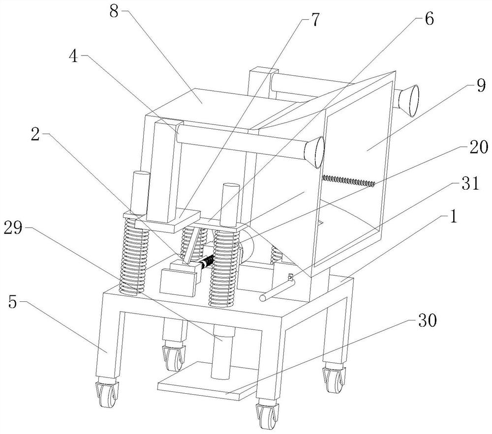
  • A wall punching device with dust suction function
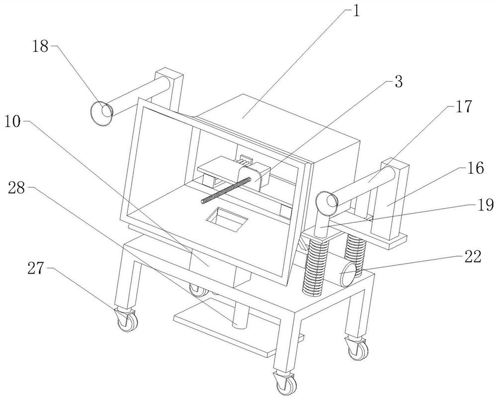
  • A wall punching device with dust suction function
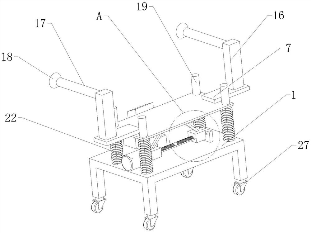
  • A wall punching device with dust suction function

Examples


Embodiment Construction

[0024] The technical solutions of the present invention will be further described below in conjunction with the accompanying drawings and through specific implementation methods.

[0025] Wherein, the accompanying drawings are only for illustrative purposes, showing only schematic diagrams, rather than physical drawings, and should not be construed as limitations on this patent; in order to better illustrate the embodiments of the present invention, some parts of the accompanying drawings will be omitted, Enlargement or reduction does not represent the size of the actual product; for those skilled in the art, it is understandable that certain known structures and their descriptions in the drawings may be omitted.

[0026] In the drawings of the embodiments of the present invention, the same or similar symbols correspond to the same or similar components; , "inner", "outer" and other indicated orientations or positional relationships are based on the orientations or positional ...


PUM


Abstract

The invention relates to the technical field of construction devices, in particular to a wall punching device with a dust-absorbing function, which includes a workbench, a lifting mechanism, a punching machine and a stabilizing mechanism. The lifting mechanism is fixedly installed on the workbench. A mounting plate is fixedly arranged on the output end, and connecting plates are fixedly arranged on both sides of the mounting plate, the stabilizing mechanism is fixedly mounted on the connecting plate, and a mounting box is fixedly mounted on the mounting plate, and the left side of the mounting box An opening is provided, a cover body is fixedly arranged on the opening, the punching machine is fixedly installed in the installation box, a dust collection box is also provided on the workbench, a suction fan is installed on the side of the dust collection box, and the dust collection box A dust suction hose connected to the cover is provided on the top, and a water delivery pipe extending into the dust collection box is also provided on the side of the dust collection box. One end of the water delivery pipeline located in the dust collection box is installed with a Universal nozzle, the device can suppress dust when drilling, purify the environment and protect human health.

Description

technical field [0001] The invention relates to the technical field of building devices, in particular to a wall punching device with a dust-absorbing function. Background technique [0002] At present, the interior decoration of many projects requires a punching machine to punch holes on the wall for installation. There are higher requirements for the holes punched in the punching work, and manual hand-held work is performed when punching holes in the high places of the wall. It will be very troublesome. The workers need to build the scaffold first, and then stand on the scaffold with a punching machine to punch holes. It is laborious to build the scaffold, and there is a very big safety hazard for the workers to stand on the scaffold to punch holes, which is harmful to the wall drilling construction. It also causes great inconvenience, and a lot of dust will be generated in the process of punching the wall, which will cause damage to the environment and human health. So n...

Claims


Application Information

Patent Timeline
Patent Type & Authority Patents(China)
IPC IPC(8): B28D1/14B28D7/00B28D7/02B28D7/04
CPCB28D1/14B28D7/00B28D7/02B28D7/046
Inventor 陈建辉周善传洪峰马维林
Owner JIANGSU NANTONG NO 2 CONSTR ENG GRP
Why Eureka
Eureka Blog
Learn More