
Device and method for sleeving wire harness with heat-shrinkable tube

A heat-shrinkable tube and wire harness technology, which is applied in the field of wire harness sleeve heat-shrinkable tube equipment, can solve the problems of time lag, poor coating quality, hot air without homogenization treatment, etc., and achieve uniform heating, good performance and smoothness Effect

Pending Publication Date: 2019-08-23
宁波拓普电器有限公司
View PDF3 Cites 3 Cited by
  • Summary
  • Abstract
  • Description
  • Claims
  • Application Information

AI Technical Summary

Problems solved by technology

[0008] The above-mentioned patent realizes the fully automatic processing of heat-shrinkable tube socket through the cooperation of various devices, and improves the processing efficiency; however, the above-mentioned patent does not perform homogenization treatment on the hot air blown out by the heat gun, and the heat at each position on the heat-shrinkable tube The amount of air accumulated is different, resulting in asynchronous phase transitions at various positions of the heat-shrinkable tube, which in turn causes a time lag in the heat-shrinking process of the heat-shrinkable tubes at different positions on the wire harness, and the coating quality of the heat-shrinkable tube on the wire harness is poor.

Method used


Image

  • Device and method for sleeving wire harness with heat-shrinkable tube
  • Device and method for sleeving wire harness with heat-shrinkable tube
  • Device and method for sleeving wire harness with heat-shrinkable tube

Examples


Embodiment

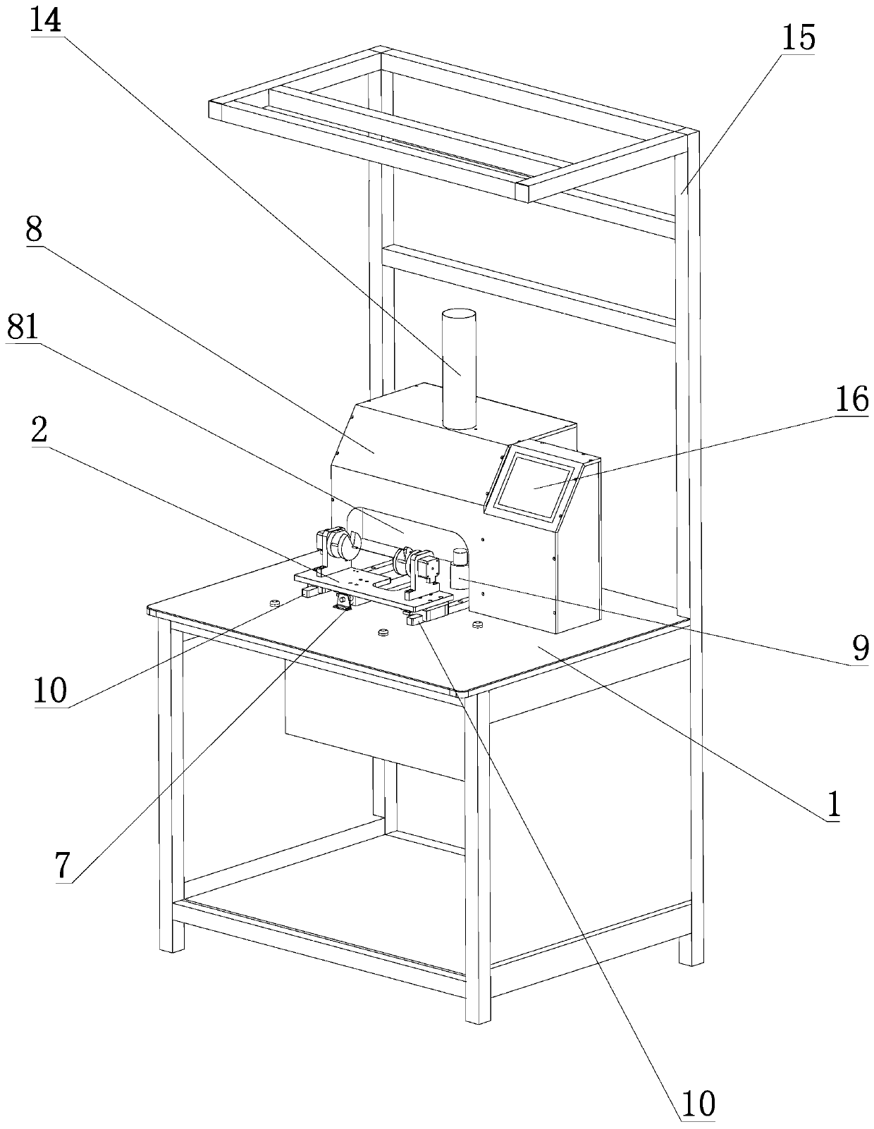
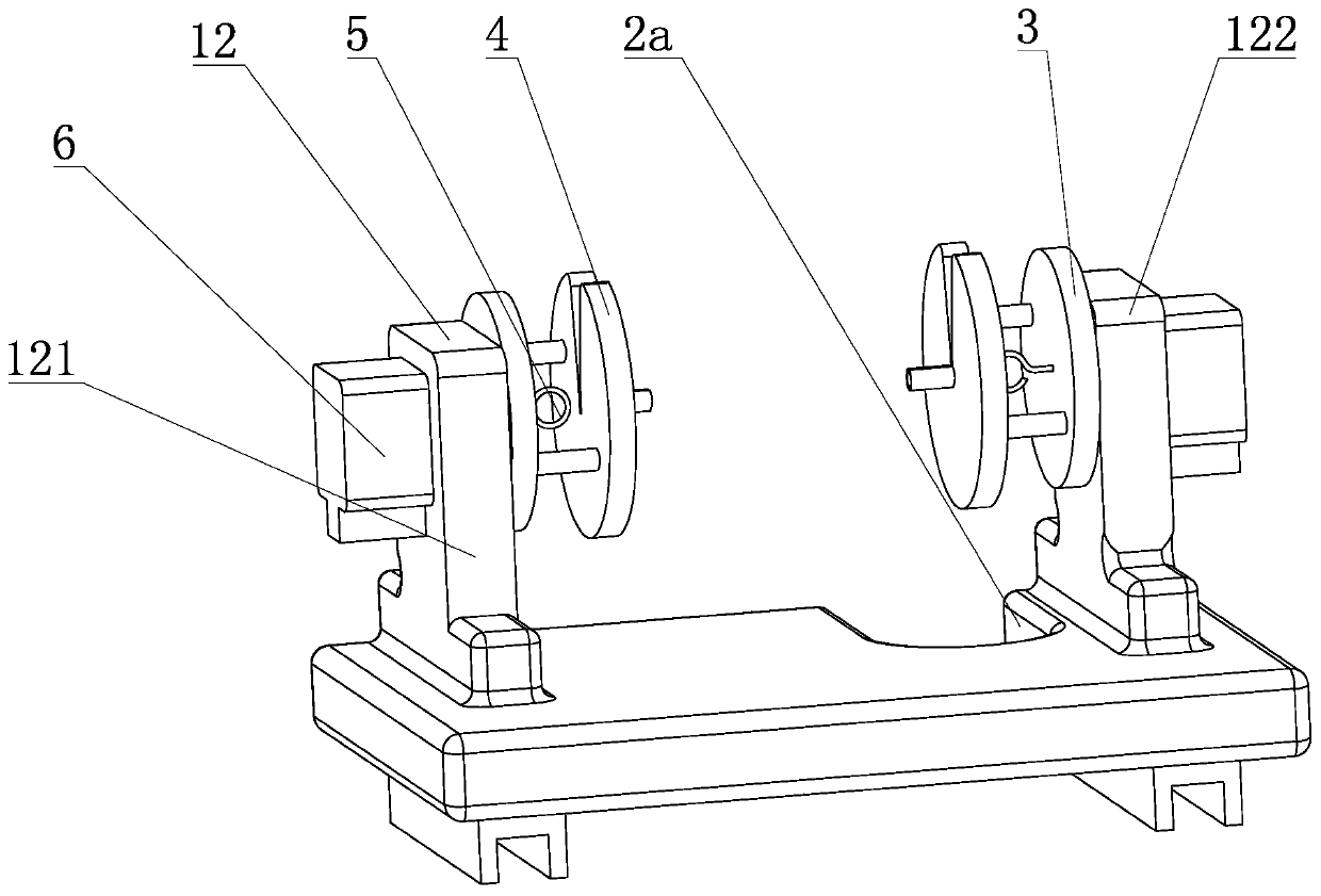
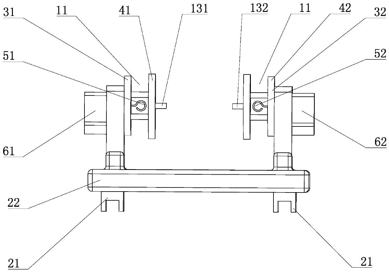
[0046] Such as Figure 1 to Figure 5 As shown, a frame 1 is included, and a mobile platform 2 is movably connected to the frame 1, and two rotating disks 3 are connected to the mobile platform 2, and the two rotating disks 3 are arranged in parallel and opposed to each other. A heat-shrinkable tube fixing block 4 for fixing the heat-shrinkable tube is fixedly connected to the two rotating disks 3 respectively, and the two heat-shrinkable tube fixing blocks 4 are arranged in parallel and opposite to each other. A wire harness fixer 5 for fixing the wire harness is connected, the rotating disc 3 is driven by a motor 6, and the frame 1 is equipped with a driving mechanism 7 for driving the mobile platform 2 to slide in and out of the heating box 8, The frame 1 is connected with a heat gun 9, the air outlet of the heat gun 9 is aligned with the gap between the two heat-shrinkable tube fixing blocks 4, and the heat gun 9 is located inside the heating box 8; The frame 1 is connecte...


PUM


Abstract

The invention relates to a device and method for sleeving a wire hardness with a heat-shrinkable tube, and aims at solving the technical problem that in the prior art, the use performance of a heat-shrinkable tube is greatly reduced due to poor coating quality of the heat-shrinkable tube on the wire harness. The device comprises a rack, wherein the rack is movably connected with a movable rack, the movable rack is connected with two rotating discs, the two rotating discs are arranged in parallel and opposite to each other, the two rotating discs are each fixedly connected with a heat-shrinkable tube fixing block used for fixing the heat-shrinkable tube, the two heat-shrinkable tube fixing blocks are arranged in parallel and opposite to each other, the two rotating discs are each connectedwith a wire harness fixing device used for fixing the wire harness, the rotating discs are driven by a motor, the rack is connected with a driving mechanism, the movable rack can slide in and slide out of a heating box under the driving of the driving mechanism, the rack is connected with a hot air gun, an air outlet of the hot air gun is aligned with the gap between the two heat-shrinkable tube fixing blocks, and the hot air gun is positioned inside the heating box. The sleeved heat-shrinkable tube has good service performance and smoothness.

Description

technical field [0001] The invention relates to the technical field of wire harness production equipment, in particular to a wire harness sleeved heat-shrinkable tube equipment and a wire harness sleeved heat-shrinkable tube method. Background technique [0002] Heat-shrinkable tubing is a special polyolefin heat-shrinkable sleeve, usually made of EVA material, which has the characteristics of high-temperature shrinkage, softness, flame retardancy, insulation and corrosion resistance. Heat-shrinkable tubes are widely used in the insulation protection of various wire harnesses, solder joints, and inductors, as well as the rust and corrosion protection of metal tubes and rods. At present, heat-shrinkable tubes are widely used in the production process of wire harnesses to realize functions such as insulation and anti-corrosion of wire harness connections. During the production process, workers usually put a section of heat-shrinkable tube on the connection of the wire harness...

Claims


Application Information

Patent Timeline
IPC IPC(8): B29C63/42B29C61/02B29C35/04
CPCB29C63/42B29C61/02B29C35/045
Inventor 叶志伟刘俊华田刚
Owner 宁波拓普电器有限公司
Learn More