
Automatic winding machine for steel cable production

A winding machine and automatic technology, applied in the field of steel cable production, can solve problems such as the influence of the service life of the steel cable and the surface corrosion of the steel cable, and achieve the effect of increasing the friction force

Pending Publication Date: 2019-08-23
天津中诚科信传动科技有限公司
View PDF1 Cites 1 Cited by
  • Summary
  • Abstract
  • Description
  • Claims
  • Application Information

AI Technical Summary

Problems solved by technology

A steel cable take-up device in the above-mentioned patent has the following disadvantages: when the steel cable is wound and rolled, a large amount of dust will adhere to the surface of the steel cable, and the dust may cause corrosion to the surface of the steel cable , thus affecting the service life of the steel cable

Method used


Image

  • Automatic winding machine for steel cable production
  • Automatic winding machine for steel cable production
  • Automatic winding machine for steel cable production

Examples


Embodiment 1

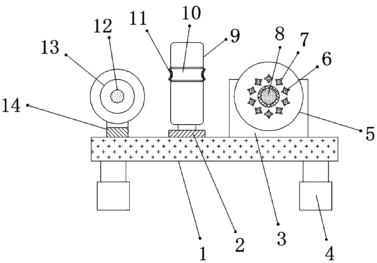
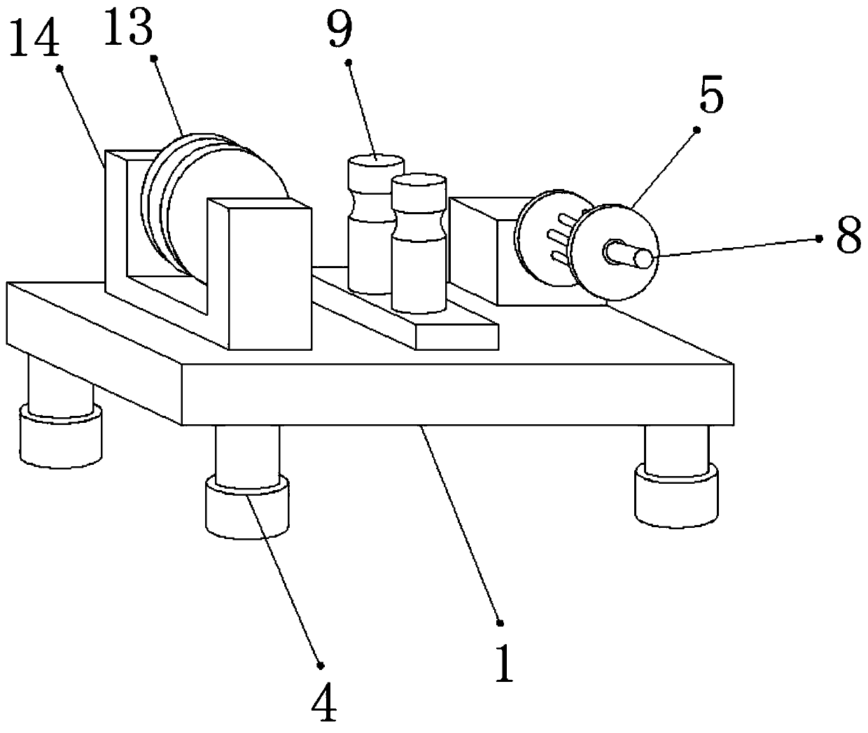
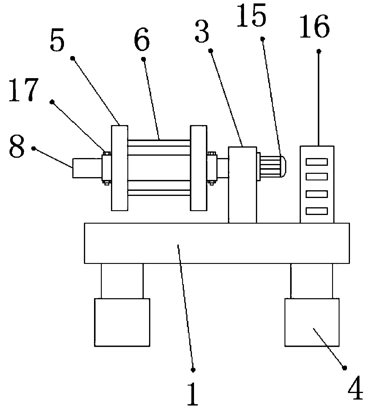
[0026] refer to Figure 1-3 , an automatic winding machine for steel cable production, comprising a fixed seat 1, one side of the outer wall of the top of the fixed seat 1 is connected with a support plate 3 by bolts, and one side of the outer wall of the support plate 3 is connected with a rotating rod 8 through a bearing rotation, and the rotation The outer wall of the rod 8 is sleeved with a winding disk 5, and the outer walls on both sides of the winding disk 5 and the outer walls on both sides of the rotating rod 8 are provided with threaded holes, and the inner walls of the threaded holes are threaded with a fixed bolt 17, and the opposite side of the winding disk 5 The side outer walls are connected with winding rods 6 by bolts, and the outer walls of the winding rods 6 are provided with convex ribs 7 distributed equidistantly. 2 Both sides of the top outer wall are rotationally connected with constraining rollers 9, and the outer walls of the two constraining rollers 9...

Embodiment 2

[0030] refer to Figure 4 , an automatic winding machine for steel cable production. Compared with Embodiment 1, the present embodiment has thread grooves on both sides of the top outer wall of the winding disc 5, and the inner walls of the two thread grooves are threaded with fixed pins 19. The outer walls of the two fixing pins 19 are threadedly connected with a constraining plate 18 .

[0031] Working principle: When in use, pass the steel cable through the restraining disc 13 and the restraining roller 9 and wind it on the winding disc 5, turn on the switch, and make the motor 15 drive the rotating rod 8 to rotate through the control box 16, so that the winding disc 5 is on the steel The cable is wound and rolled, and the friction force between the steel cable and the winding rod 6 is increased through the rib 7, so that the steel cable is wound, and the winding disc 5 is prevented from idling due to the relatively smooth surface of the steel cable. , the steel cable will...


PUM


Abstract

The invention discloses an automatic winding machine for steel cable production. The automatic winding machine comprises a fixing seat and is characterized in that a support plate is fixed to one sideof the outer wall of the top of the fixing seat, a rotary rod is rotatably connected to the outer wall of one side of the support plate through a bearing, a winding plate is connected to the outer wall of the rotary rod in a sleeved manner, the outer walls on two sides of the winding plate and the outer walls on two sides of the rotary rod are provided with threaded holes, fixing bolts are connected to the inner walls of the threaded holes in a threaded manner, a winding rod is fixed between the outer walls of the opposite sides of the winding plate, flanges distributed in an equal-distance manner are arranged on the outer wall of the winding rod, and a fixing plate is fixed to a positon, close to the middle, of the outer wall of the top of the fixing seat. By the automatic winding machine, steel cable service life shortening caused by the fact the surface of the steel cable is corroded by dust can be prevented, the influence of winding plate idling caused by steel cable surface smoothness on steel cable winding can be prevented, and steel cable collapse caused by excessively large steel cable winding height can be prevented.

Description

technical field [0001] The invention relates to the technical field of steel cable production, in particular to an automatic winding machine for steel cable production. Background technique [0002] The steel cable is a steel wire bundle twisted by a plurality of multi-strand steel wire ropes around a fiber core or steel wire rope core. deposit. [0003] After searching, the Chinese patent application number is CN206244181U patent, which discloses a steel cable take-up device, including a base and a motor, a vertical central shaft is installed in the center of the base, and a concentric turntable is fixed on the upper end of the central shaft. U-shaped support plates arranged radially are evenly distributed on the circumferential wall, and vertically arranged steel cable inner diameter fixing columns are fixed on the U-shaped supporting plates, and all steel cable inner diameter fixing columns are located on concentric circles, and the The output shaft of the motor is conn...

Claims


Application Information

Patent Timeline
Patent Type & Authority Applications(China)
IPC IPC(8): D07B7/10D07B7/02
CPCD07B7/02D07B7/10
Inventor 王煜李锡英
Owner 天津中诚科信传动科技有限公司
Learn More