
Roller brush

A roller brush and roller technology, applied in construction, building structure and other directions, can solve the problems of increasing the work intensity of construction workers, reducing the work efficiency of construction workers, inconvenient paint replenishment, etc., so as to improve the brushing efficiency and save resources. , Easy to clean or replace

Active Publication Date: 2019-08-23
DANYANG XINHE BRUSHING IND CO LTD
View PDF9 Cites 3 Cited by
  • Summary
  • Abstract
  • Description
  • Claims
  • Application Information

AI Technical Summary

Problems solved by technology

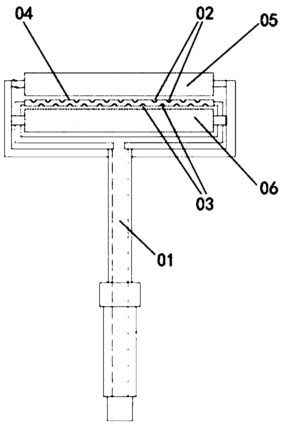
[0003] This method greatly increases the work intensity of the construction personnel, and also reduces the work efficiency of the construction personnel. In order to solve the above technical problems, such as figure 1 As shown, a Chinese utility model patent "Rolling brush assembly for construction (publication number: CN 208858119U)" discloses a rolling brush structure that can automatically feed materials, and has an upper spray hole 02 and a The nozzle 04 of the lower nozzle hole 03 is used for automatic feeding, wherein, the upper roller brush 05 and the lower roller brush 06 are respectively arranged on both sides of the nozzle 04, and the nozzle 04 is sandwiched between the two roller brushes , and during the painting process, the paint from the upper nozzle hole 02 and the lower nozzle hole 03 is received continuously for painting, thus effectively improving the efficiency of painting and avoiding the difficulty of operation caused by manual dipping of the paint , but in the above process, since the nozzle 04 is exposed outside, it is inevitable that there will be paint splashes, and it is inevitable that there will be problems that the paint is difficult to control at the beginning and end of the painting
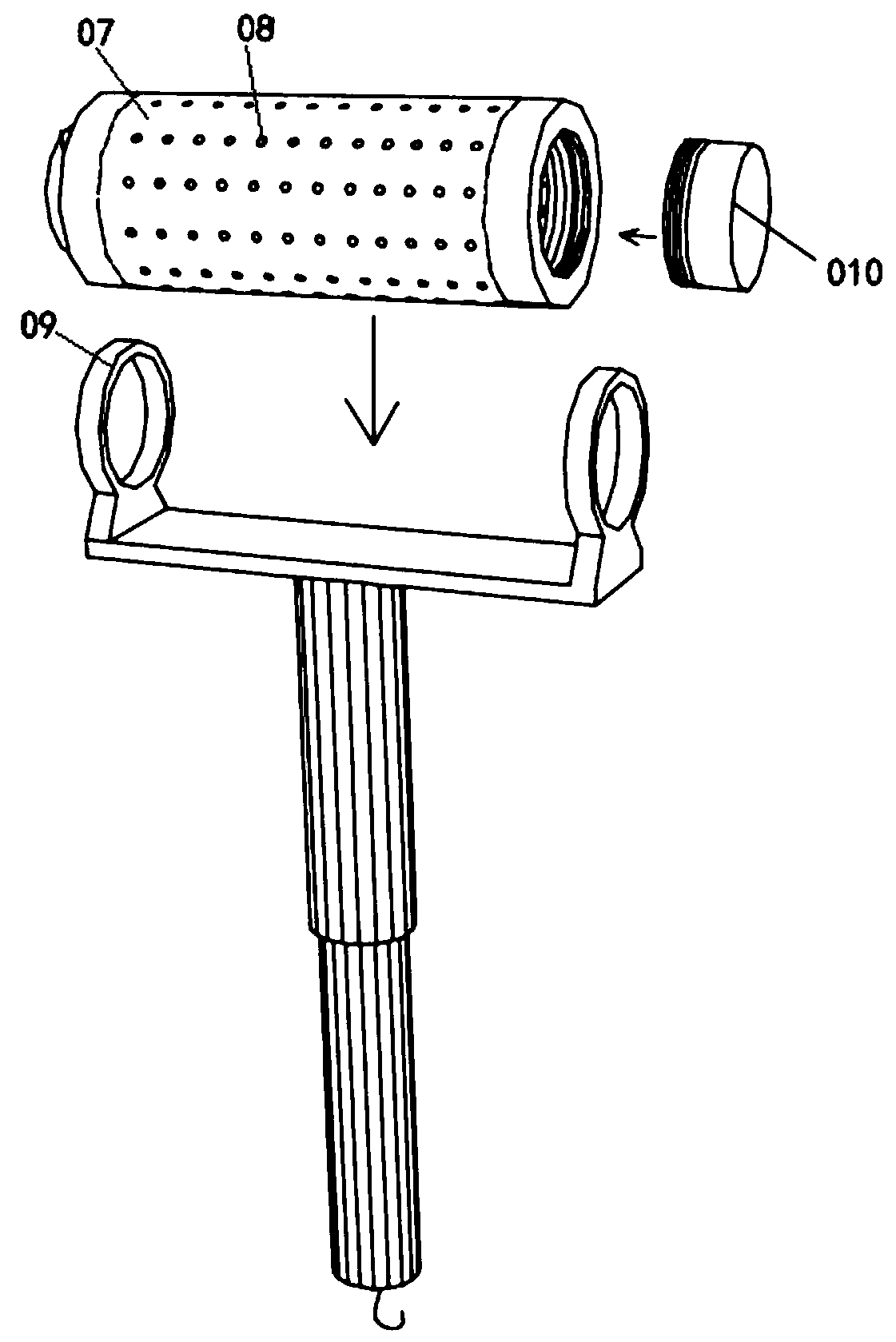
[0004] like figure 2 As shown, a Chinese utility model patent "A kind of internal paint storage type roller paint brush (publication number: CN208899824U)" discloses a paint brush with a paint storage cavity, the cavity is set inside the roller brush cover 07, And the roller brush cover 07 allows the paint located in the storage cavity to flow out to the outside of the roller brush cover 07 through the grout hole 08 provided on the side wall for coating, but in the above structure, the roller brush cover 07 is coated. During installation, there is a risk of separation between it and the bracket 09, because the paint needs to be replenished after the roller plug 010 is removed, and the roller plug 010 is the fixing and cavity sealing element of the roller brush cover 07, Therefore there is the inconvenient problem of coating replenishment in above-mentioned structure

Method used


Image

  • Roller brush
  • Roller brush
  • Roller brush

Examples


Embodiment Construction

[0047] The following will clearly and completely describe the technical solutions in the embodiments of the present invention with reference to the accompanying drawings in the embodiments of the present invention. Obviously, the described embodiments are only some, not all, embodiments of the present invention.

[0048]In the description of the present invention, it should be noted that the terms belonging to "center", "upper", "lower", "left", "right", "vertical", "horizontal", "inner", "outer" etc. The indicated orientation or positional relationship is based on the orientation or positional relationship shown in the drawings, and is only for the convenience of describing the present invention and simplifying the description, rather than indicating or implying that the referred device or element must have a specific orientation, or in a specific orientation. construction and operation, therefore, should not be construed as limiting the invention.

[0049] In the description...


PUM


Abstract

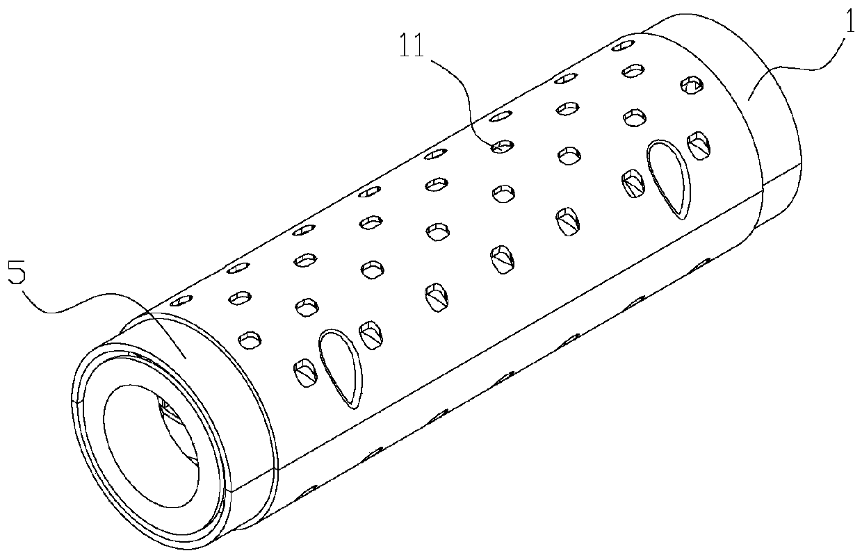
The invention relates to a roller brush which comprises a roller structure, a mounting bracket and a flow diversion pipe. The roller structure is used for mounting and supporting a brushing fabric; aplurality of slurry-permeating holes are formed in the roller structure; the mounting bracket at least comprises a handle, a first supporting part and a second supporting part; the flow diversion pipeis used for mounting the roller structure; the two ends of the flow diversion pipe are separately fixed through the first supporting part and the second supporting part; a first cavity is formed in the middle of the flow diversion pipe; an opening in one axial end communicates with the outside; coating is supplemented by means of the opening; after the coating is supplemented, the opening is plugged by a seal cover; a slurry outlet hole is formed in the side wall of the first cavity, and is used for communicating the first cavity with a second cavity between the flow diversion pipe and the roller structure; and the coating flowing in the second cavity from the first cavity flows out from the slurry-permeating hole. The roller brush is simple in structure and convenient to operate, and slurry is poured in the flow diversion pipe to realize self supply of the coating in brushing conveniently, so that the long-time coating brushing is ensured, the brushing efficiency is improved, and theoperation difficulty is reduced.

Description

technical field [0001] The invention relates to a roller brush. Background technique [0002] In the traditional building painting process, when painting the building wall, the operator needs to operate through the painting handle, and repeatedly dip the paint to make it adsorbed on the fabric outside the roller brush , and in the process of rolling and extruding the fabric and the wall, it is applied to the surface of the wall to complete the painting. [0003] This method greatly increases the work intensity of the construction personnel, and also reduces the work efficiency of the construction personnel. In order to solve the above technical problems, such as figure 1 As shown, a Chinese utility model patent "Rolling brush assembly for construction (publication number: CN 208858119U)" discloses a rolling brush structure that can automatically feed materials, and has an upper spray hole 02 and a The nozzle 04 of the lower nozzle hole 03 is used for automatic feeding, whe...

Claims


Application Information

Patent Timeline
Patent Type & Authority Applications(China)
IPC IPC(8): E04F21/06
CPCE04F21/06
Inventor 高光明高杨
Owner DANYANG XINHE BRUSHING IND CO LTD
Learn More