Friction plate

A friction plate and friction material technology, applied in the direction of friction linings, friction clutches, clutches, etc., can solve many problems such as torque transmission, and achieve the effect of reducing resistance torque, improving cooling performance, and improving cooling performance.

Inactive Publication Date: 2019-08-23
DAINATSUKUSU
View PDF10 Cites 1 Cited by
  • Summary
  • Abstract
  • Description
  • Claims
  • Application Information

AI Technical Summary

Problems solved by technology

However, in fact, due to the lubricating oil between the mating plate and the friction plate, the transmission of torque between the mating plate and the friction plate is not much

Method used


Image

  • Friction plate
  • Friction plate
  • Friction plate

Examples


Embodiment Construction

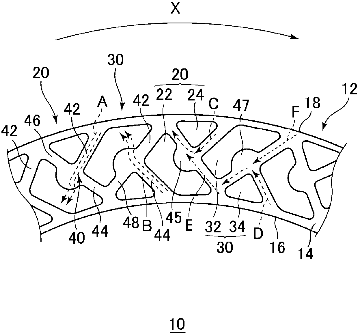
[0049] Below, refer to the attached Figure 1~3 Embodiments of the present invention will be described. However, the present invention is not limited to these embodiments. In addition, although the friction plate of this invention is used for a friction clutch, since the basic structure of a friction clutch is well-known, description accompanying illustration of a friction clutch itself is abbreviate|omitted.

[0050] Such as figure 1 As shown, in the friction plate 10 of the present invention, on the surface 14 of the plate 12, the first friction material group 20 and the second friction material group 30 are attached alternately in the circumferential direction, and the first friction material group 20 consists of a pair of opposite The first segment 22 located on the inner peripheral side and the second segment 24 located on the outer peripheral side, the second friction material group 30 is composed of a pair of third segment 32 located on the outer peripheral side and a...


PUM


Abstract

The invention provides a friction plate which is relatively small in drag torque and is improved in cooling performance. According to the friction plate (10), when a friction clutch is not engaged, lubricating oil flowing to the inner circumferential side from an outer circumferential oil tank (42) flows to the position above a first section (22) of a first friction material group (20). On the other hand, lubricating oil flowing to the outer circumferential side from an inner circumferential oil tank (44) flows to the position above a third section (32) of a second friction material group (30), so that the lubricating oil is discharged axially, and the gap between the friction plate (10) and a matching plate is expanded to play a role. The drag torque can be reduced by increasing the content of air in the lubricating oil. When the friction clutch is engaged, the lubricating oil flows out of the friction plate through an outer circumferential communicating oil tank (46) or an inner circumferential communicating oil tank (48). Therefore, the heat exchange efficiency is improved, so that the cooling performance can be further improved.

Description

technical field [0001] The present invention relates to a friction plate for a friction clutch which frictionally engages a friction plate (wet friction plate) soaked in lubricating oil with a mating plate to transmit torque. Background technique [0002] A friction clutch generally includes a plurality of engaging plates that rotate in conjunction with one shaft, and friction plates that are arranged between the engaging plates and rotate in association with the other shaft. Also, the piston acts and presses the mating plate to frictionally engage the mating and friction plates, thereby transmitting torque between one shaft and the other. The mating plate and the friction plate are immersed in lubricating oil, and the mating plate and the friction plate are cooled by the lubricating oil. Friction materials are attached to surfaces (both surfaces) of the friction plate that face the mating plate. Furthermore, oil grooves for flowing lubricating oil are provided on the surf...

Claims


Application Information

Patent Timeline
Patent Type & Authority Applications(China)
IPC IPC(8): F16D13/64F16D13/72F16D13/74F16D69/00
CPCF16D13/64F16D13/72F16D13/74F16D69/00
Inventor 高仓则雄萨加达·艾哈迈德·巴洛夫及川明人大桥亮
Owner DAINATSUKUSU
Why Eureka
Try Eureka