
A water level sensor automatic debugging machine

A water level sensor and automatic debugging technology, applied in instruments, test/calibration devices, measuring devices, etc., can solve problems such as inability to integrate debugging and testing, inability to automatically fix fixtures, unfavorable rapid and continuous operation, etc., to improve the use of range, ease of detection, and the effect of increasing device utilization

Active Publication Date: 2020-07-31
中山市博胜机电设备有限公司
View PDF6 Cites 0 Cited by
  • Summary
  • Abstract
  • Description
  • Claims
  • Application Information

AI Technical Summary

Problems solved by technology

[0004] Aiming at the deficiencies of the prior art, the present invention provides an automatic water level sensor debugging machine, which solves the problem that the water level sensor debugging equipment proposed in the above background technology does not have the function of replacing the water level test with air pressure, which makes the device detection time-consuming and unnecessary. It is conducive to rapid and continuous operation, reduces the operating efficiency of the device, cannot simulate the pressure of different gears, and cannot perform integrated operations for debugging and testing. The related fixtures used for debugging cannot be automatically fixed, and manual operations are required, which increases the labor intensity of the staff. The problem

Method used


Image

  • A water level sensor automatic debugging machine
  • A water level sensor automatic debugging machine
  • A water level sensor automatic debugging machine

Examples


Embodiment Construction

[0027] The following will clearly and completely describe the technical solutions in the embodiments of the present invention with reference to the accompanying drawings in the embodiments of the present invention. Obviously, the described embodiments are only some, not all, embodiments of the present invention.

[0028] In the description of the present invention, unless otherwise stated, the meaning of "plurality" is two or more; the terms "upper", "lower", "left", "right", "inner", "outer" , "front end", "rear end", "head", "tail", etc. indicate the orientation or positional relationship based on the orientation or positional relationship shown in the drawings, and are only for the convenience of describing the present invention and simplifying the description, rather than Nothing indicating or implying that a referenced device or element must have a particular orientation, be constructed, and operate in a particular orientation should therefore not be construed as limiting ...


PUM


Abstract

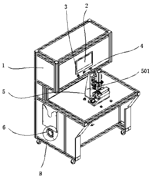
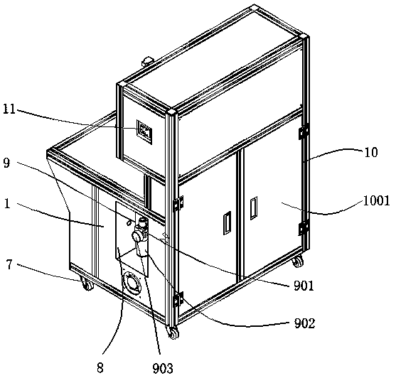
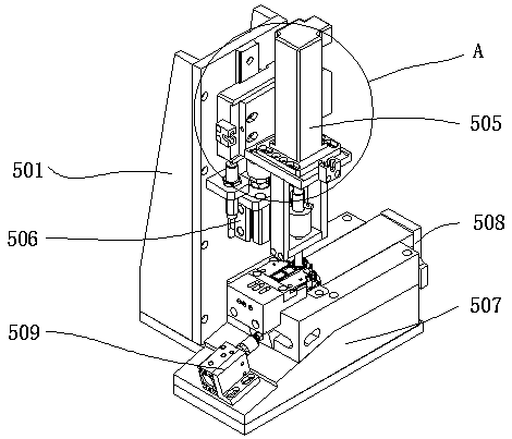
The invention discloses an automatic adjustment machine for water level sensors, relates to the technical field of adjustment devices for water level sensors, in particular to an automatic adjustment machine for water level sensors, comprising a main frame and a power switch, the outer wall of the main frame is provided with a touch screen, and the touch screen An indicator light is placed below the indicator light, the power switch is placed on one side of the indicator light, a fixing mechanism is arranged on the top of the main frame, and a cooling mechanism is arranged on the right side of the outer wall of the main frame, and a cooling mechanism is arranged on the bottom of the main frame The bottom wheel, and the other side of the outer wall of the main frame is provided with a reserved groove, and a filtering mechanism is arranged inside the reserved groove. The water level sensor automatic debugging machine, through the outer wall of the touch screen and the outer wall of the main frame is on the same horizontal line, so that when the device is in use, the user's body will not touch the touch screen, preventing the user from touching the screen by mistake, causing the device to fail to operate normally , improve the stability of device operation, and indirectly increase the service life of the touch screen.

Description

technical field [0001] The invention relates to the technical field of a debugging device for a water level sensor, in particular to an automatic debugging machine for a water level sensor. Background technique [0002] The water level sensor is an instrument that can convert the water level parameter of the measured point into a corresponding electrical signal in real time. It is widely used in water plants, oil refineries, chemical plants, oil wells, oil tanks, oil pools, and various static and dynamic liquid levels. For measurement and control, when the water level sensor is produced, it is necessary to debug the water level sensor to ensure the accuracy of the later use of the sensor. At this time, a professional water level sensor debugging machine is needed to debug the sensor and increase the quality of the finished product after processing. Rate. [0003] At present, most of the industry still uses manual debugging. The existing water level sensor debugging equipmen...

Claims


Application Information

Patent Timeline
Patent Type & Authority Patents(China)
IPC IPC(8): G01F25/00
CPCG01F25/00G01F25/20
Inventor 申健罗明华张文
Owner 中山市博胜机电设备有限公司
Learn More