
Mars probe charging system and charging control method

A Mars rover, Mars technology, applied in the direction of secondary battery charging/discharging, battery circuit devices, circuits, etc., can solve the problems of solar panels unable to provide electricity, and achieve the effect of improving service life and high efficiency

Inactive Publication Date: 2019-08-23
ZHENGZHOU UNIV OF IND TECH
View PDF7 Cites 0 Cited by
  • Summary
  • Abstract
  • Description
  • Claims
  • Application Information

AI Technical Summary

Problems solved by technology

When the Mars rover faces away from the sun or encounters a sandstorm covering the solar panels, the solar panels will not be able to provide power to the rover.

Method used


Image

  • Mars probe charging system and charging control method
  • Mars probe charging system and charging control method
  • Mars probe charging system and charging control method

Examples


Embodiment Construction

[0032] In order to make the purpose, features and effects of the present invention more obvious and understandable, the specific implementation manners of the present invention will be described in detail below in conjunction with the accompanying drawings.

[0033] Many specific details are set forth in the following description to facilitate a full understanding of the present invention, but the present invention can also be implemented in other ways than described here, so the present invention is not limited by the specific embodiments disclosed below.

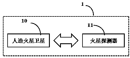
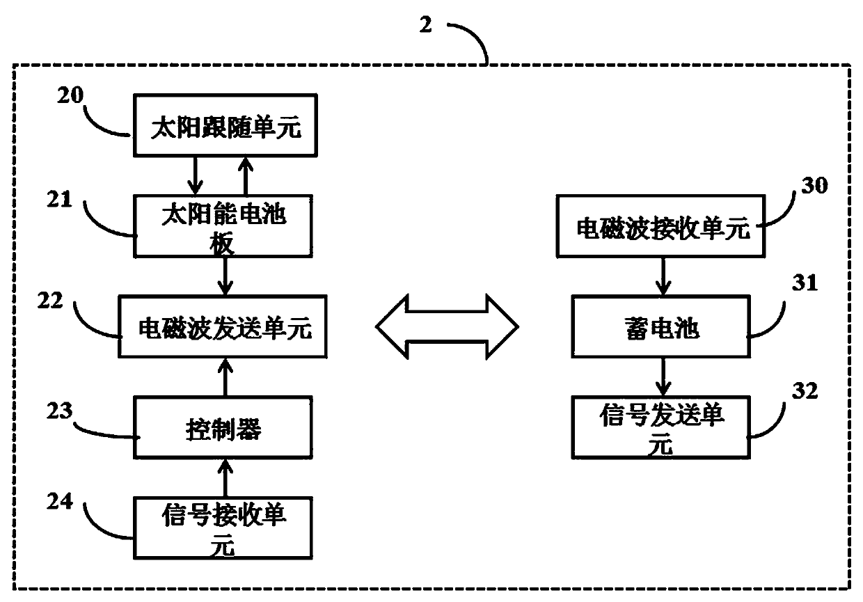
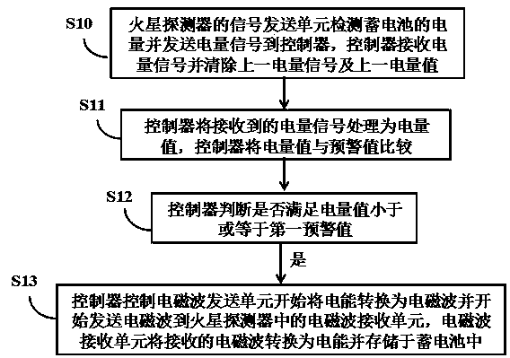
[0034] The application first provides a Mars rover charging system 1, such as figure 1 As shown, it includes: an artificial Mars satellite 10 and a Mars probe 11; the artificial Mars satellite 10 has a solar panel and an electromagnetic wave sending unit; the Mars probe 11 has an electromagnetic wave receiving unit and a storage battery. The solar panels of the artificial Mars satellite 10 convert solar energy into electri...


PUM


Abstract

The invention relates to a Mars probe charging system and a charging control method. The system comprises at least one artificial Mars satellite and a Mars probe. The Mars probe charging system can continuously provide electric energy for the Mars probe.

Description

technical field [0001] The invention relates to the field of outer space probes, in particular to a Mars probe charging system and a method for controlling charging thereof. Background technique [0002] Electromagnetic waves are oscillating particle waves that are derived and emitted in space by electric and magnetic fields that are in phase and perpendicular to each other. They are electromagnetic fields that propagate in the form of waves and have wave-particle duality. The speed of electromagnetic waves in vacuum is the speed of light. Electromagnetic waves are mainly divided into radio waves, microwaves, infrared rays, visible light, ultraviolet rays, X-rays and gamma rays from low frequency to high frequency. The radio wave charging method is a charging technology that converts electrical energy into electromagnetic waves, and the receiver converts the electromagnetic waves into electrical energy after receiving it. [0003] Human beings have been curious about outer...

Claims


Application Information

Patent Timeline
Patent Type & Authority Applications(China)
IPC IPC(8): H02J7/00H02J50/00H01M10/44H01M10/48
CPCH02J7/00H02J50/00H02J7/0029H01M10/48H01M10/44Y02E60/10
Inventor 欧阳富
Owner ZHENGZHOU UNIV OF IND TECH
Learn More