Split core unit, rotary electric machine, method for manufacturing split core unit, and method for manufacturing rotary electric machine
A manufacturing method and core technology, applied in the manufacture of stator/rotor bodies, motor generators, electromechanical devices, etc., can solve problems such as inability to arrange magnetic wires, shifting positional relationship of split iron cores, and deterioration of coil arrangement. Achieve the effect of easy production change
- Summary
- Abstract
- Description
- Claims
- Application Information
AI Technical Summary
Problems solved by technology
Method used
Image

Examples
Embodiment approach 1
[0056]Next, the split iron core unit, the rotating electric machine, the manufacturing method of the split iron core unit, and the manufacturing method of the rotating electric machine according to Embodiment 1 of the present invention will be described with reference to the drawings.
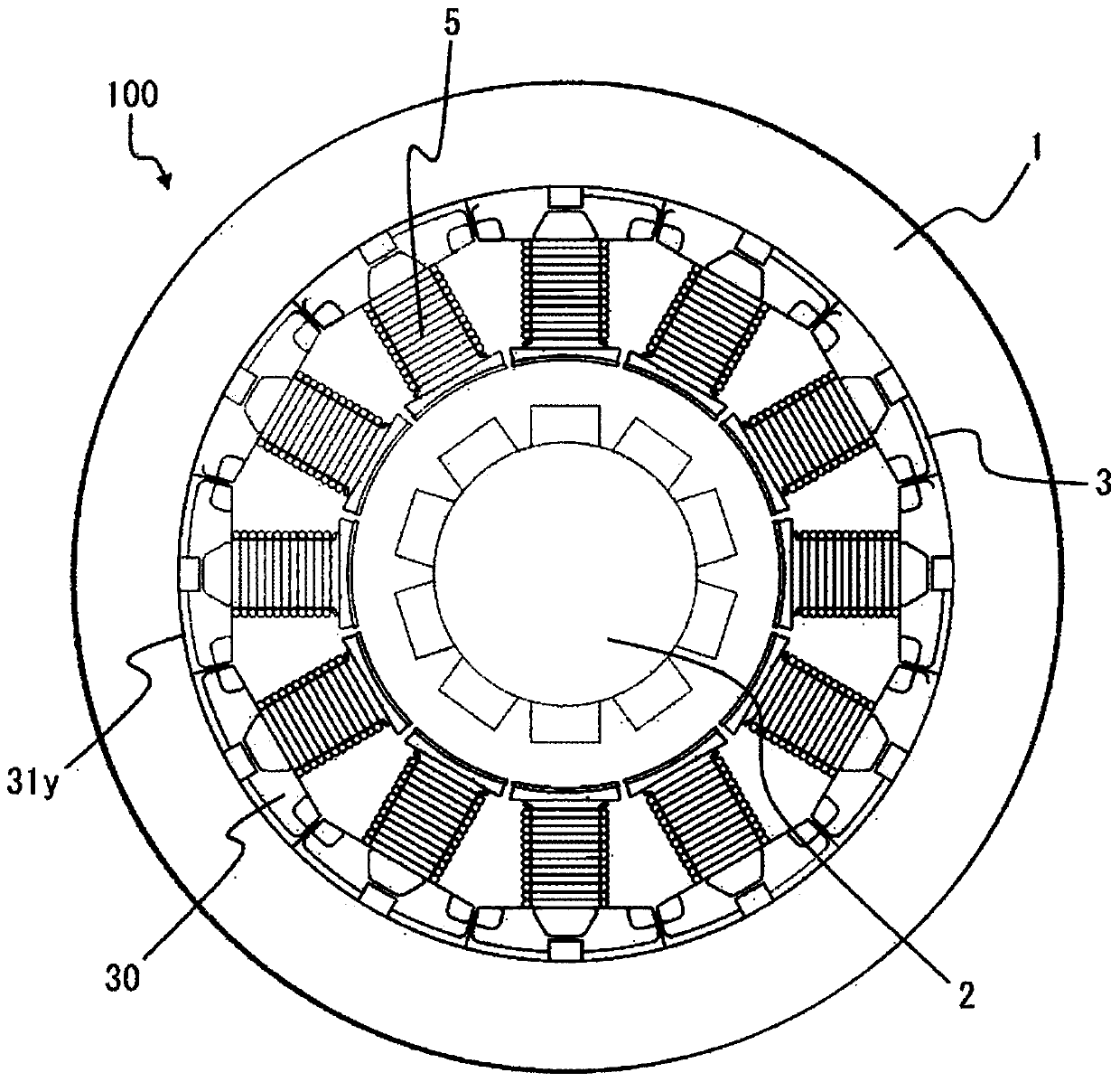
[0057] In this specification, when referring to "axial direction", "circumferential direction", "radial direction", "inner peripheral side", "outer peripheral side", "inner peripheral surface" and "outer peripheral surface" unless otherwise specified, It is assumed that the stator combined with split core units refers to the "axial direction", "circumferential direction", "radial direction", "inner peripheral side", "outer peripheral side", "inner peripheral surface", " peripheral surface". In addition, in this specification, when referring to "upper" and "lower" unless otherwise specified, a plane perpendicular to the axial direction is assumed as a place of reference, and an area including th...
Embodiment approach 2
[0106] Next, the split iron core unit, the rotating electric machine, the manufacturing method of the split iron core unit, and the manufacturing method of the rotating electric machine according to Embodiment 2 of the present invention will be described with reference to the drawings.
[0107] Figure 11 It is a front view showing the winding method when using the connecting core.
[0108] In Embodiment 1, the magnetic wire W is wound on the split core unit intermediate body 30A having the split cores 31 scattered at random, but in this embodiment, the circumferential ends of the plurality of split cores 231 are Winding is performed by connecting a sheet or an insulating member that can be connected.
[0109] By connecting the plurality of split cores 231 , it is possible to manufacture the stator 3 with a split core unit in an annular shape with good workability. In addition, the circumferential end portions of the core pieces constituting the split core 231 are connected ...
Embodiment approach 3
[0115] Next, the split core unit, the rotating electrical machine, the manufacturing method of the split iron core unit, and the manufacturing method of the rotating electrical machine according to Embodiment 3 of the present invention will be described with reference to the drawings.
[0116] Figure 12A It is a front view of split core unit intermediate body 330A.
[0117] Figure 12B It is a figure which shows the fixed state of the holder 379 and two 1st groove|channel 304k and 2nd groove|channel 331k.
[0118] A first groove 304k extending in the axial direction and having a T-shaped cross section perpendicular to the axial direction is formed in the circumferential center portion of the outer peripheral surface of the yoke covering portion 304y. A second groove 331k extending in the axial direction across the entire length of the split core 331 and having a T-shaped cross section perpendicular to the axial direction is formed in the circumferential center portion of th...
PUM
 Abstract
Description
Claims
Application Information
 - R&D
- Intellectual Property
- Life Sciences
- Materials
- Tech Scout
- Unparalleled Data Quality
- Higher Quality Content
- 60% Fewer Hallucinations
Browse by: Latest US Patents, China's latest patents, Technical Efficacy Thesaurus, Application Domain, Technology Topic, Popular Technical Reports.
© 2025 PatSnap. All rights reserved.Legal|Privacy policy|Modern Slavery Act Transparency Statement|Sitemap|About US| Contact US: help@patsnap.com