Portable toilet bowl
A portable, toilet technology, applied in the field of daily necessities, can solve the problems of lack of universality for users, cold and uncomfortable touch, weak ground contact, etc., and achieve the effects of easy fixing of the toilet, increased friction coefficient, and simple structure.
- Summary
- Abstract
- Description
- Claims
- Application Information
AI Technical Summary
Problems solved by technology
Method used
Image
Examples
Embodiment 1
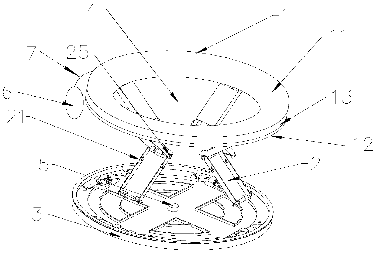
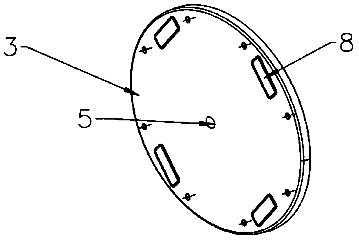
[0037] Refer to attached Figure 1-5 , the portable toilet includes a toilet seat 1 and a base 3 correspondingly arranged up and down, the toilet seat 1 and the base 3 are connected by a foldable frame body 2, and the foldable frame body 2 is composed of a plurality of circumferential The set folding brackets 21 are enclosed; the number of the folding brackets 21 is 3-5, preferably 4. The foldable frame body 2 has a cavity 4 communicating with the toilet seat 1, and each foldable frame can be folded inward.
[0038] The folding bracket 21 includes an upper frame body 22 and a lower frame body 23, the upper end of the upper frame body 22 is flexibly connected with the toilet seat 1, and the lower end of the upper frame body 22 is flexibly connected with the lower frame body 23; correspondingly, the lower frame body The lower end is movably connected with the base 1, and the other end is movably connected with the lower end of the upper frame. The connection between the upper ...
Embodiment 2
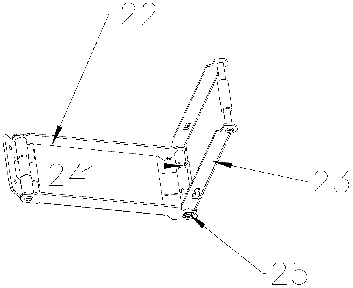
[0048] On the basis of Example 1, such as Figure 6-9 As shown, the upper frame body 22 and the lower frame body 23 are connected by a locking structure, and the locking structure includes a rotating shaft 24 connected between the upper and lower frame bodies and can cooperate with the rotating shaft 24 to make the upper and lower frame bodies The screw knobs 25 that cannot be moved relative to each other, the upper frame body 22 and the toilet seat 1, and the lower frame body 23 and the base 3 are all rotationally and foldably connected.
[0049] Specifically, the lower end of the upper frame body 22 and the upper end of the lower frame body 23 are provided with bushings, the rotating shaft 24 passes through the lower end of the upper frame body 22 and the upper end of the lower frame body 23, and one end of the rotating shaft 24 is provided with a fixed cap 27 In order to make it impossible to enter and exit the bushing, the other end extends to the outside of the bushings o...
Embodiment 3
[0055] On the basis of Example 2, such as Figure 10 As shown, one end of the rotating shaft 24 connected to the screw button 25 is provided with a protruding portion 241 extending outwards and having a diameter smaller than the rotating shaft, and the protruding portion 241 is provided with an external thread. The structure sleeved on the rotating shaft is a screw button 25. The center of the screw button 25 is provided with a screw hole matched with the protruding part. See attached Figure 10 ) is provided with a flared mouth 251 with a diameter greater than that of the rotating shaft 24, so that during the tightening process of the screw button 25, the rotating shaft 24 can enter the flared opening 251, so that the end surface of the screw button 25 close to the second epitaxial sheet 231 can be supported on the second epitaxial sheet 231. On the sheet 231, the force is applied or transmitted to the second epitaxial sheet 231, and the second epitaxial sheet 231 transmits ...
PUM
 Abstract
Description
Claims
Application Information
 - R&D
- Intellectual Property
- Life Sciences
- Materials
- Tech Scout
- Unparalleled Data Quality
- Higher Quality Content
- 60% Fewer Hallucinations
Browse by: Latest US Patents, China's latest patents, Technical Efficacy Thesaurus, Application Domain, Technology Topic, Popular Technical Reports.
© 2025 PatSnap. All rights reserved.Legal|Privacy policy|Modern Slavery Act Transparency Statement|Sitemap|About US| Contact US: help@patsnap.com


