
Simplified punching die

A mold and punching technology, applied in the field of simplified punching molds, can solve the problems of no competitive advantage, long mold production cycle, high product price, and achieve the effects of simple and practical processing and development, easy portability and transportation, and low processing costs.

Inactive Publication Date: 2019-08-27
十堰卓环汽车零部件有限公司
View PDF0 Cites 0 Cited by
  • Summary
  • Abstract
  • Description
  • Claims
  • Application Information

AI Technical Summary

Problems solved by technology

[0005] In order to solve the above-mentioned technical problems, the present invention provides a simplified punching die to solve the above-mentioned background technology. The more commonly used punching die is a standard punching die with a mold frame, which has a complicated structure and high cost, resulting in the product The price is also high, and there is no competitive advantage; in addition, some products are now in trial production, and the projects that have not been mass-produced may be terminated. The use of standard mold base molds leads to losses. The problem

Method used


Image

  • Simplified punching die
  • Simplified punching die
  • Simplified punching die

Examples


Embodiment

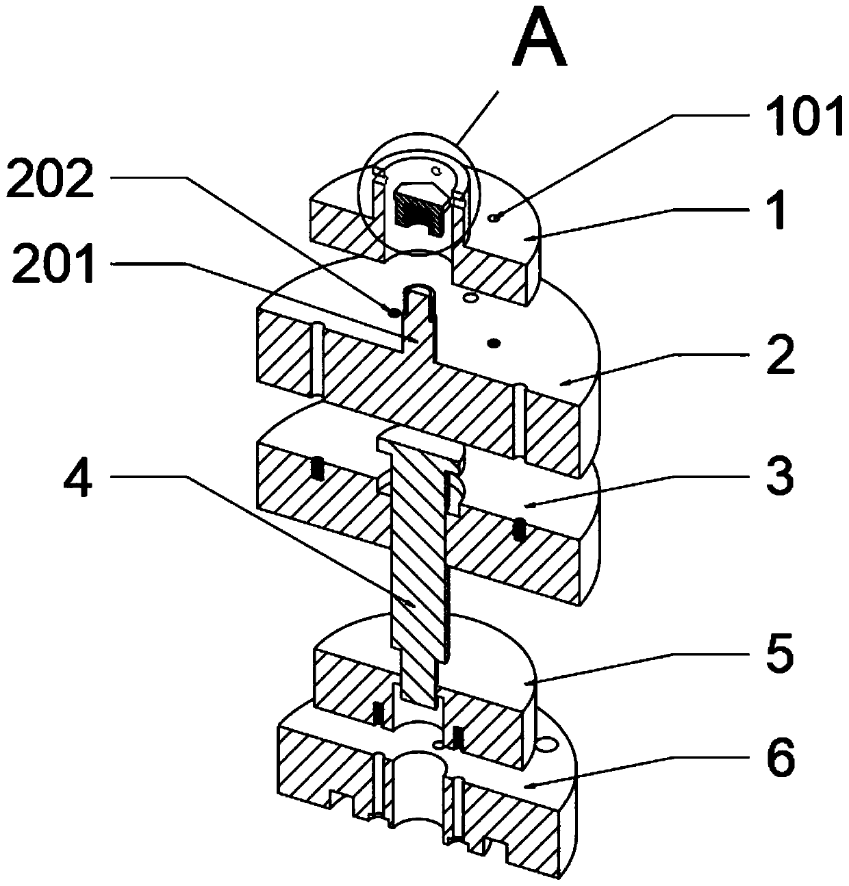
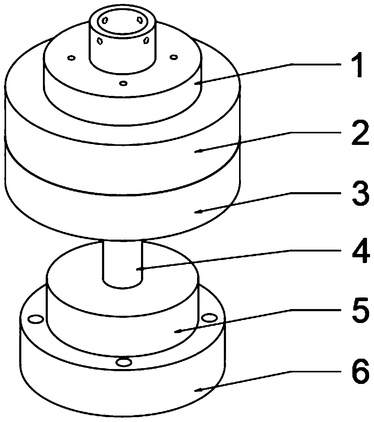
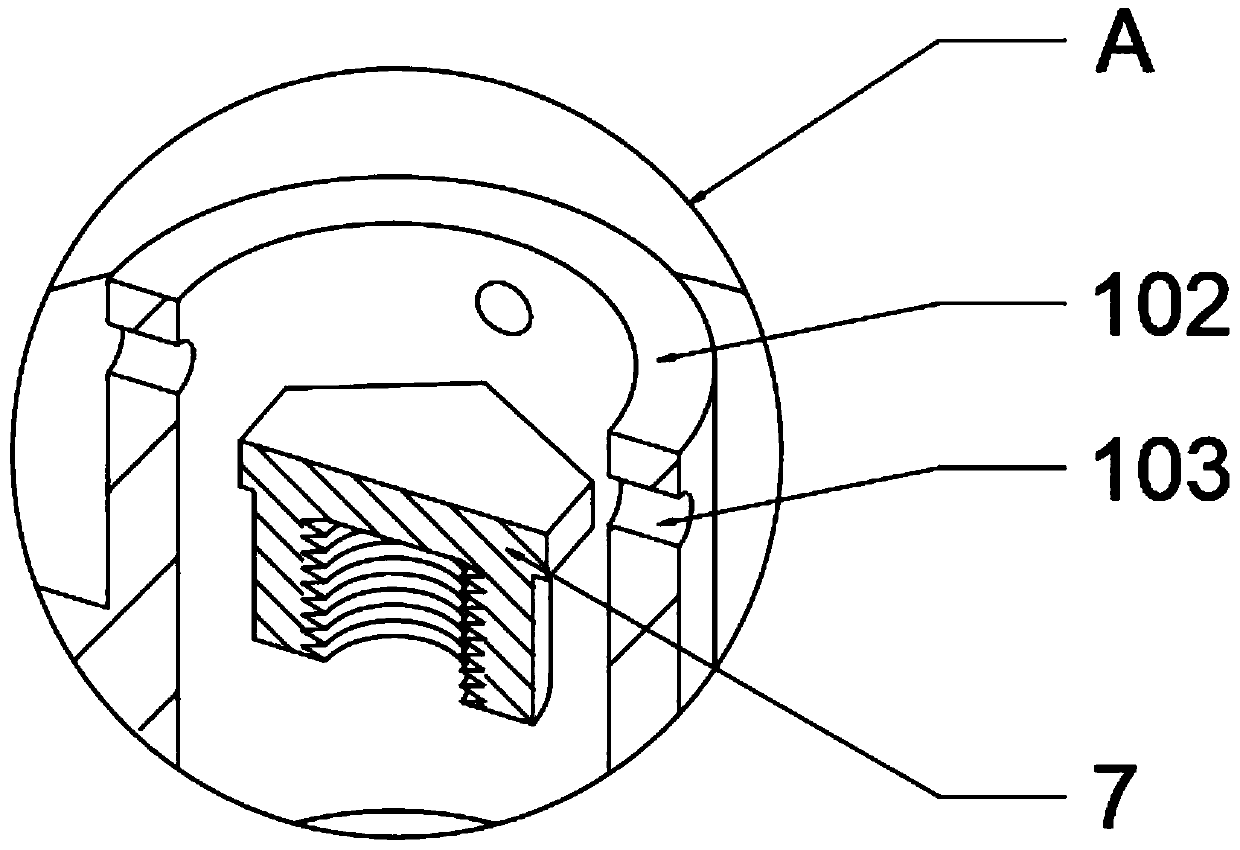
[0024] as attached figure 1 to attach image 3 Shown:

[0025] The present invention provides a simplified punching die, which includes a die handle 1, a die handle through hole 101, a die handle barrel 102, a circumferential position control hole 103, an upper template 2, a connecting rod 201, an auxiliary screw hole 202, and a punch fixing plate 3. Punch 4, die 5, bottom plate 6 and screw cap 7; four groups of die handles 1 are provided with four groups of die handle through holes 101; four groups of auxiliary screw holes 202 are provided around the top of the upper template 2, And the upper template 2 passes through the mold handle through hole 101 through the screw and inserts the auxiliary screw hole 202 to be positioned and connected with the mold handle 1; four groups of through holes are provided around the middle of the upper template 2; four groups of the punch fixing plate 3 are provided with Four sets of screw holes, and a T-shaped hole is opened in the middle of...


PUM


Abstract

The invention provides a simplified punching die which comprises die handles, die handle through holes, a die handle cylinder, a circumferential position-control hole, an upper die plate, a connectingrod, auxiliary screw holes, punch fixing plates, punches, a female die, a bottom plate and a thread cap. The four groups of die handles are provided with the four groups of die handle through holes;the four groups of auxiliary screw holes are formed in the periphery of the top part of the upper die plate; the upper die plate is in positioning connection with the die handles through a way that screws penetrate through the die handle through holes so as to be inserted into the auxiliary screw holes; the four groups of through holes are formed in the periphery of the middle of the upper die plate; the four groups of punch fixing plates are provided with four groups of screw holes; and a T-shaped hole is formed in the middle of each punch fixing plate. Through arranging the die handle cylinder and the connecting rod, double functions are provided for the assembling the die handles and the upper die plate, so that the stress resistance of the die is effectively improved, and convenience is provided for punching; and the circumferential position-control hole is formed outside the die handle cylinder, so that the die handle cylinder can be conveniently aligned and fixed and is conveniently matched with mechanical equipment for use, and the flexible practicability and the installation applicability of the die are improved.

Description

technical field [0001] The invention belongs to the technical field of automobile manufacturing industry, and more specifically relates to a simplified punching die. Background technique [0002] In the automotive industry, parts often fail to meet the actual use requirements (especially the hole requirements) during later loading, which leads to rectification of the mold or the addition of corresponding simple molds to meet the requirements in the later stage; however, some parts in the original Changes on the mold cannot realize its new process content. In this case, it is often necessary to redevelop the mold. [0003] Based on the above, the more commonly used punching dies are standard stamping dies with a mold base, the structure is relatively complicated, and the cost is relatively high, resulting in high product prices and no competitive advantage; Projects without volume are terminated, and molds using standard mold bases lead to losses, and the losses outweigh the...

Claims


Application Information

Patent Timeline
Patent Type & Authority Applications(China)
IPC IPC(8): B21D28/34
CPCB21D28/34
Inventor 李金涛阮红超陈龙赖亮王秀林黄强卓文武
Owner 十堰卓环汽车零部件有限公司
Learn More