
Probe

A probe and needle body technology, applied in the field of probes, can solve problems such as low efficiency and cumbersome operation, achieve the effect of reducing clamping positions, reducing material turnover, and meeting the tolerance requirements of drawings

Active Publication Date: 2019-08-27
GUANGDONG EVERWIN PRECISION TECH
View PDF5 Cites 0 Cited by
  • Summary
  • Abstract
  • Description
  • Claims
  • Application Information

AI Technical Summary

Problems solved by technology

[0004] Based on this, it is necessary to provide a probe capable of detecting multiple different positions of the same product for the problems that different types of probes need to be used when probing different positions of the same product, the operation is cumbersome, and the efficiency is low.

Method used


Image

  • Probe
  • Probe
  • Probe

Examples


Embodiment Construction

[0026] In order to make the above objects, features and advantages of the present invention more comprehensible, specific implementations of the present invention will be described in detail below in conjunction with the accompanying drawings. In the following description, numerous specific details are set forth in order to provide a thorough understanding of the present invention. However, the present invention can be implemented in many other ways different from those described here, and those skilled in the art can make similar improvements without departing from the connotation of the present invention, so the present invention is not limited by the specific implementations disclosed below.

[0027] It should be noted that when an element is referred to as being “fixed” to another element, it can be directly on the other element or there can also be an intervening element. When an element is referred to as being "connected to" another element, it can be directly connected ...


PUM


Abstract

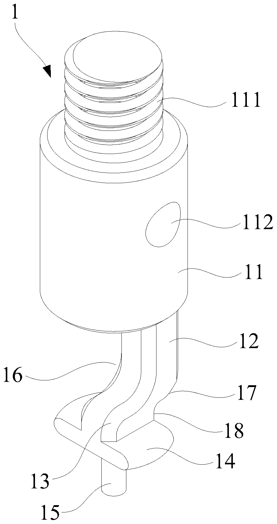
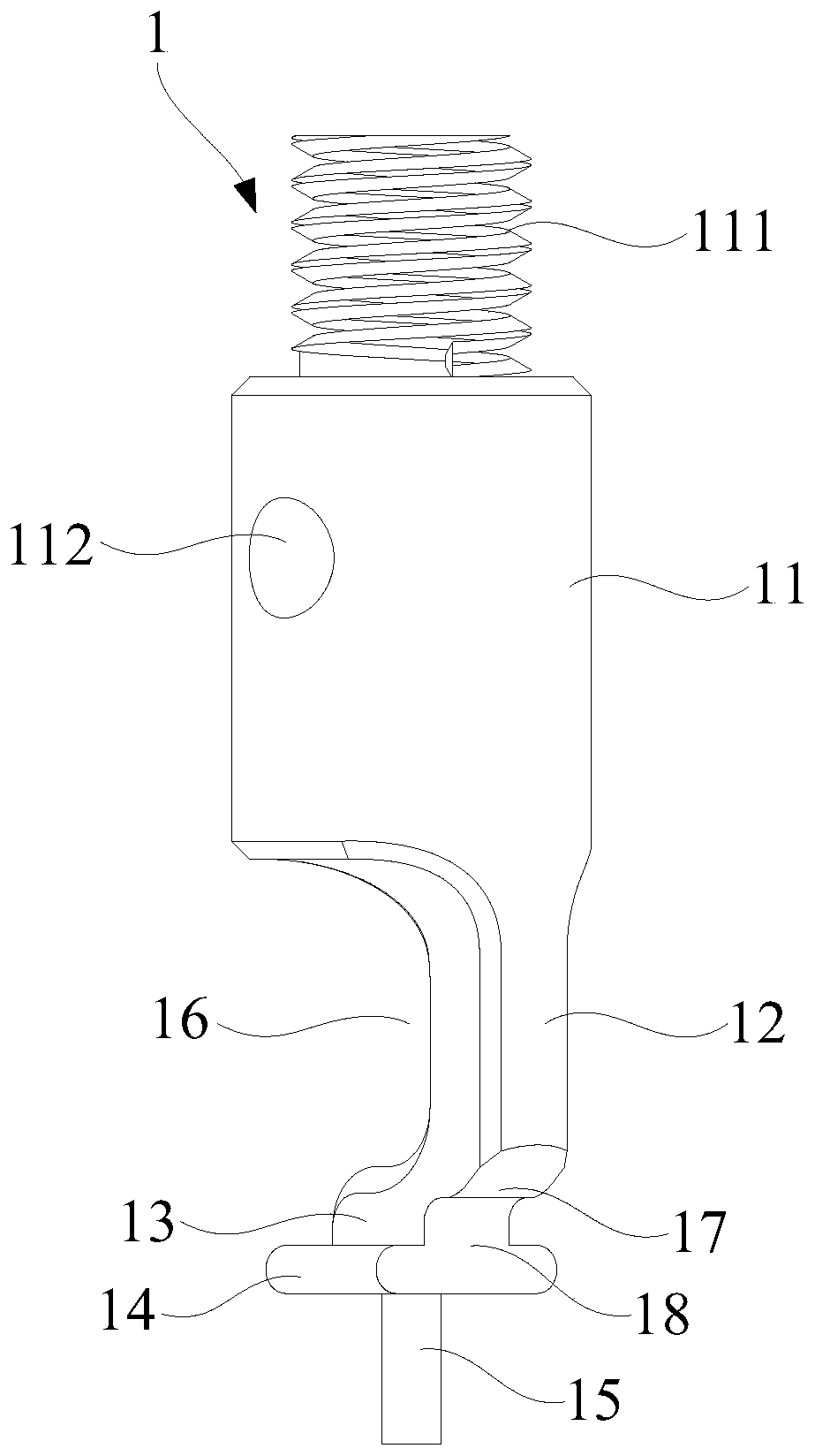
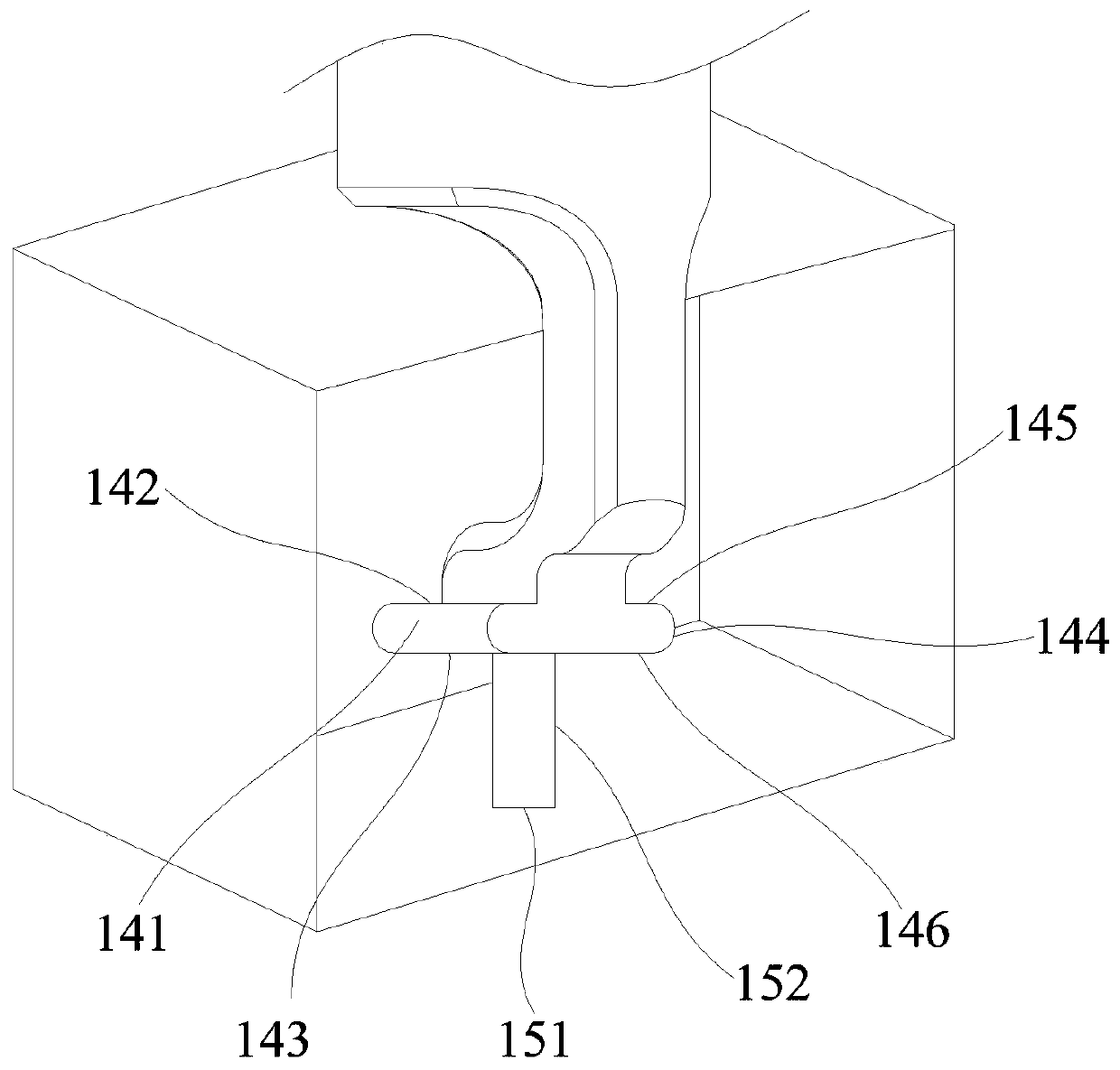
The invention relates to a probe. The probe comprises a needle body, a first connecting arm, a second connecting arm, a first detection head and a second detection, wherein the needle body comprises afirst end and a second end, and the first end can be fixedly connected with a machine tool clamping position; the first connecting arm comprises a first end and a second end, wherein the first end ofthe first connecting arm is connected with the second end of the needle body, and the second end of the first connecting arm extends along the axial direction of the needle body to be away from the needle body; the second connecting arm comprises a first end and a second end, wherein the first end of the second connecting arm is connected with the second end of the first connecting arm, the second end of the second connecting arm extends along the radial direction of the needle body, and a clearance part is formed among the second end of the needle body, the first connecting arm and the second connecting arm; the first detection head is arranged on the second connecting arm; and the second detection head is arranged on one side, away from the second connecting arm, of the first detectionhead. The probe is capable of detecting a plurality of different positions of one product.

Description

technical field [0001] The invention relates to the technical field of CNC machining detection, in particular to probes. Background technique [0002] In the prior art, it is usually necessary to detect different positions of the same product, so as to improve the processing accuracy requirements, ensure better matching accuracy of the products, and smoother activities. [0003] Due to the large differences in the structure of each position of the same product, such as hole structure, slide rail groove structure, round hole structure, waist hole structure, etc., it is necessary to use different types of probes when detecting structures at different positions of the same product. It is impossible to directly detect all positions through ordinary probes, L-shaped probes, etc., which requires setting multiple clamping positions on the CNC machining machine and installing a variety of different probes for the detection of different positions of the same product. Different probe...

Claims


Application Information

Patent Timeline
IPC IPC(8): B23Q17/20
CPCB23Q17/20
Inventor 刘思其
Owner GUANGDONG EVERWIN PRECISION TECH
Learn More