Detection method and detection system for belt tearing state of belt conveyor

A state detection and conveyor technology, applied in the direction of conveyor objects, conveyor control devices, transportation and packaging, etc., can solve the problem that the belt is difficult to find, impossible to monitor the real-time running state of the belt in real time and accurately, and human contact equipment. Low detection accuracy and other problems, to reduce economic losses and avoid major production accidents

Active Publication Date: 2021-06-15
天津市三特电子有限公司
View PDF0 Cites 0 Cited by
  • Summary
  • Abstract
  • Description
  • Claims
  • Application Information

AI Technical Summary

Problems solved by technology

[0003] At present, abnormal states such as belt tearing can only be judged by manual detection or contact detection equipment (sensors). However, in actual production, it is difficult to find various abnormal states of the belt in the early stage. The detection accuracy of contact equipment is low, and it is impossible to monitor the real-time running status of the belt in real time and accurately. Therefore, when the belt is found to be abnormal, various major losses of the equipment have occurred and are irreparable.

Method used


Image

  • Detection method and detection system for belt tearing state of belt conveyor
  • Detection method and detection system for belt tearing state of belt conveyor
  • Detection method and detection system for belt tearing state of belt conveyor

Examples


Embodiment 1

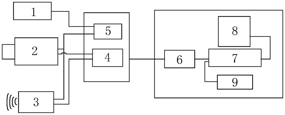
[0039] Such as figure 1 and figure 2As shown, the belt conveyor belt tear state detection system includes an image acquisition unit, a defect location unit, a transmission unit and a data processing unit; wherein,

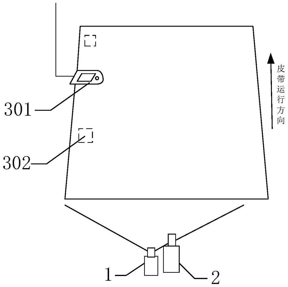
[0040] The imaging unit includes an image acquisition device 2 arranged on one side of the belt and a laser light source 1 arranged on the adjacent side of the image acquisition device; specifically,

[0041] The image acquisition device 2 is a camera arranged in a protective cover and a zoom lens matched with the camera. The installation height of the image acquisition device 2 is lower than the installation height of the belt, and the camera lens faces the non-working surface of the belt (ie, the back of the belt) Set so that the width of the captured image exceeds the width of the belt;

[0042] In this embodiment, since the installation height of the belt is 450mm, the installation height of the image acquisition equipment is 300mm, which is lower than the i...

Embodiment 2

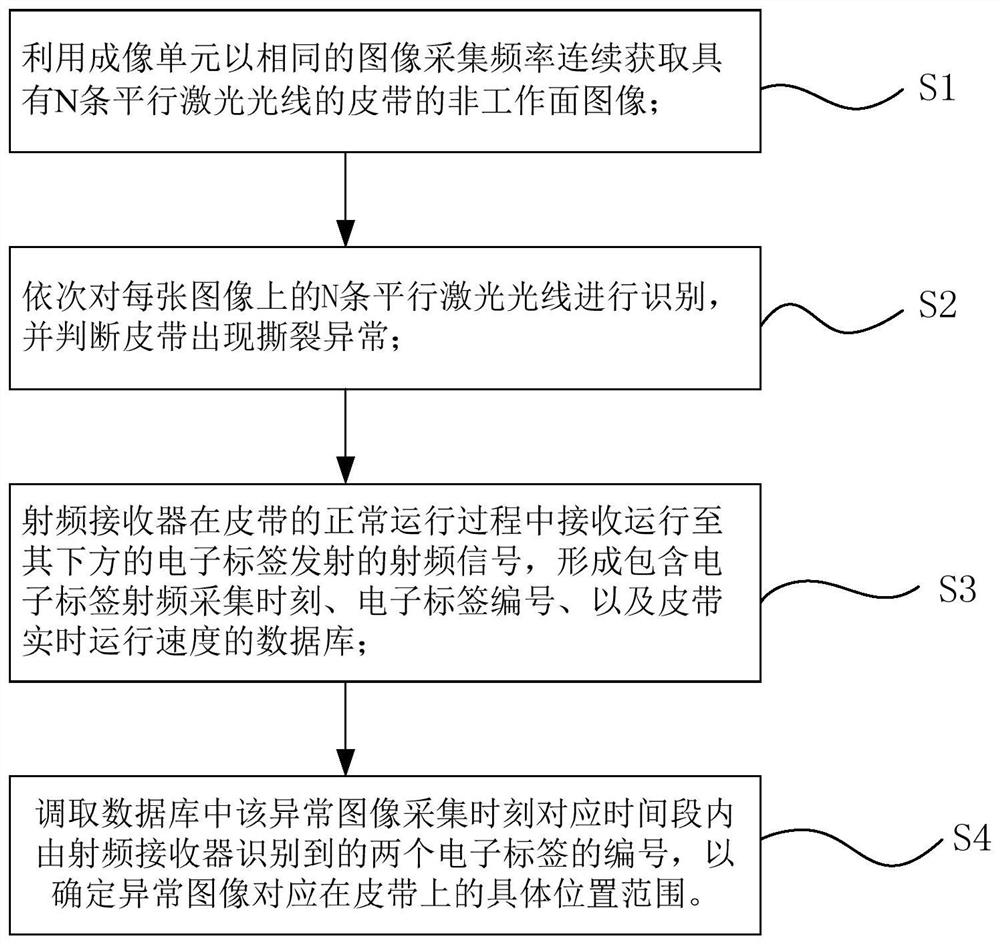
[0056] Such as image 3 As shown, a detection method implemented by a belt conveyor belt tear state detection system, the specific steps are as follows:

[0057] S1. Use the imaging unit to continuously acquire images of the non-working surface of the belt with 11 parallel laser rays at the same image acquisition frequency; wherein, the distance between two adjacent laser rays is 20 mm;

[0058] Among them, since the position of the laser light relative to the camera is fixed, the position of the laser light in the image is also fixed after the installation is completed, so the camera's setting position is adjusted to each laser light on the image collected during the debugging stage Keep the same length, brightness and clarity, and each laser line has no breakpoints, such as Figure 4 As shown; if the image acquisition range is large, the target image can also be intercepted in the image collected by the camera by setting the coordinate position of the target image to obtain...


PUM


Abstract

The invention discloses a detection system and detection method for the belt tear state of a belt conveyor. The method comprises sequentially performing 1) continuously acquiring non-working surface images of a belt with N parallel laser rays, and 2) identifying each image 3) The radio frequency receiver receives the radio frequency signal of the electronic tag embedded in the belt and forms an information database, 4) Determines the corresponding position of the abnormal image on the belt; its detection system includes An imaging unit for acquiring non-working surface images of a belt with N parallel laser rays, a defect location unit for belt location, and a corresponding data processing unit and transmission unit; the method and system adopt non-contact video monitoring technology , to realize real-time monitoring of belt running status, automatic detection of belt tear status and timely detection of hidden dangers of belt abnormalities, to avoid major production accidents.

Description

technical field [0001] The invention relates to the technical field of a continuous monitoring device for working conditions in a furnace and a production process, in particular to a detection method and a detection system for a belt tear state of a belt conveyor. Background technique [0002] Belt conveyors are widely used in mining, metallurgy, electric power, steel and other industries. However, due to the long-term operation of the conveyor belt and the influence of various accidental factors, abnormal states such as belt tearing, scratching, stalling and deviation occur frequently during belt operation. If the conveyor belt can be alarmed and repaired in time, it can be avoided. production accidents and reduce economic losses. [0003] At present, abnormal states such as belt tearing can only be judged by manual detection or contact detection equipment (sensors). However, in actual production, it is difficult to find various abnormal states of the belt in the early sta...

Claims


Application Information

Patent Timeline
Patent Type & Authority Patents(China)
IPC IPC(8): B65G43/02
CPCB65G43/02B65G2207/40
Inventor 张海根
Owner 天津市三特电子有限公司
Why Eureka
Try Eureka